Roller bearing capable of realizing self-power-generation monitoring

A kind of roller bearing and self-generating technology, applied in the direction of roller bearing, rolling contact bearing, bearing of rotating motion, etc., can solve the problems of magnetic interference, depolarization of piezoelectric ceramics, small size, etc.

Active Publication Date: 2021-05-04
ZHEJIANG NORMAL UNIVERSITY
View PDF4 Cites 2 Cited by
  • Summary
  • Abstract
  • Description
  • Claims
  • Application Information

AI Technical Summary

Problems solved by technology

At present, most of the bearings with self-power supply monitoring function are generated by using electromagnetic and piezoelectric principles. The disadvantages of electromagnetic power generation are magnetic interference and weak power generation capacity at low speeds. The disadvantages of piezoelectric power generation are that the additional space required is relatively large. When the temperature is too high, it will cause depolarization of piezoelectric ceramics
Obviously, the existing technology still has great limitations in practical application, and various bearings with self-powered monitoring functions that are small in size and highly integrated, especially suitable for high-temperature environments, are still urgently needed by various industries.

Method used


Image

  • Roller bearing capable of realizing self-power-generation monitoring
  • Roller bearing capable of realizing self-power-generation monitoring
  • Roller bearing capable of realizing self-power-generation monitoring

Examples


Embodiment Construction

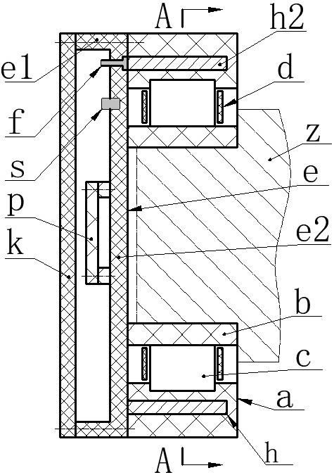
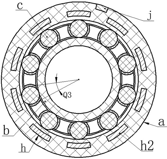
[0018] The present invention proposes a self-generating and monitoring roller bearing, which mainly includes an inner ring b, an outer ring a, a roller c, a bracket d, a shell e, a sensor s and a circuit board p.

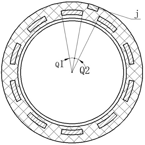
[0019] There is an annular raceway on the inner edge of the outer ring a, the outer ring a is installed on the inner ring b through the bracket d and the roller c, and the roller c is embedded in the raceway of the outer ring a; the shell bottom e2 of the shell e It is installed on the end of the outer ring a or inner ring b through screws, the end of the shell wall e1 is installed with an end cover k through screws, and the circuit board p, sensor s, and terminal f are installed on the bottom e2 of the shell. An auxiliary electrode j is provided on the ring a, and the sensor s, the terminal f and the auxiliary electrode j are connected to the circuit board p through different wire groups.

[0020] There is an electrode h inside the outer ring a or inner ring b, the...


PUM


Abstract

The invention relates to a roller bearing capable of realizing self-power-generation monitoring, and belongs to the technical fields of bearing monitoring and new energy. An outer ring is arranged on an inner ring, a shell bottom is arranged at the end part of the outer ring, a circuit board, a sensor and a binding post are arranged on the shell bottom, an auxiliary electrode is arranged on the shell bottom or the outer ring, and the sensor, the binding post and the auxiliary electrode are connected with the circuit board through different conductive wire groups; an electrode is arranged in the outer ring, the outer ring is of a split structure or an integral structure, the electrode is composed of an electrode ring, electrode fingers and a lead terminal, the electrode ring and the electrode fingers are embedded in the outer ring, and rollers are not overlapped with the electrode ring in the length direction and is completely overlapped with the electrode fingers; different friction charges can be generated in the rolling contact process of the rollers and the outer ring, and the rollers are alternately overlapped with and separated from the electrode fingers in the rolling process, so that the potential difference between the rollers and the electrode fingers is alternately increased and decreased, and then mechanical energy is converted into electric energy; and the generated electric energy is supplied to the sensor and a transmitting unit on the circuit board after being processed by a conversion circuit on the circuit board.

Description

technical field [0001] The invention belongs to the technical field of bearing monitoring and new energy, and in particular relates to a roller bearing for self-generating monitoring. Background technique [0002] Bearings are indispensable standard parts in the fields of machine tools, transportation tools, mining machinery and light industrial machinery, and are also one of the most vulnerable parts in related transmission systems. 30% of rotating machinery failures are caused by bearing failures. Therefore, bearing condition monitoring and early fault diagnosis have attracted people's attention. On-line monitoring of bearings and their transmission systems has become a prerequisite for reliable operation of related equipment in the fields of generators, ships, high-speed rail, and aircraft. The performance indicators to be monitored include temperature, vibration, speed, and noise. The initial bearing monitoring system is mainly a split external structure, which belongs ...

Claims


Application Information

Patent Timeline
IPC IPC(8): F16C19/36F16C33/62F16C33/34F16C41/00H02N1/04
CPCF16C19/361F16C33/62F16C33/34F16C41/00H02N1/04F16C2233/00
Inventor 王淑云任泽峰杨泽萌陈松曹红兵吴鸣程光明曾平
Owner ZHEJIANG NORMAL UNIVERSITY
Why Eureka
Try Eureka