Residential composite exhaust passage and mounting method thereof

An installation method and exhaust duct technology, which are applied in vertical pipes, building components, buildings, etc., can solve the problems of easy deformation, distortion, poor sealing effect, and deep bending, and achieve good sealing performance, easy installation, and strength. Good results

Inactive Publication Date: 2021-05-04
杭州润泉环境科技有限公司
View PDF16 Cites 0 Cited by
  • Summary
  • Abstract
  • Description
  • Claims
  • Application Information

AI Technical Summary

Problems solved by technology

[0009] The purpose of the present invention is to solve the problems that the existing residential exhaust duct system is prone to deformation, distortion, and deep bending during long-term use, and the existing exhaust duct will form a certain connection between floors There are gaps, the sealing effect is poor, and there will be smoke leakage during use, but a method that can effectively strengthen the deformation, twisting, deep bending and vertical bearing capacity of the pipe body is provided, and it is easy to install, and there will be no connection gaps, sealing Residential compound exhaust duct with good effect and beautiful appearance and its installation method

Method used


Image

  • Residential composite exhaust passage and mounting method thereof
  • Residential composite exhaust passage and mounting method thereof
  • Residential composite exhaust passage and mounting method thereof

Examples


Embodiment 1

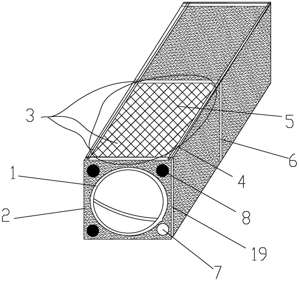
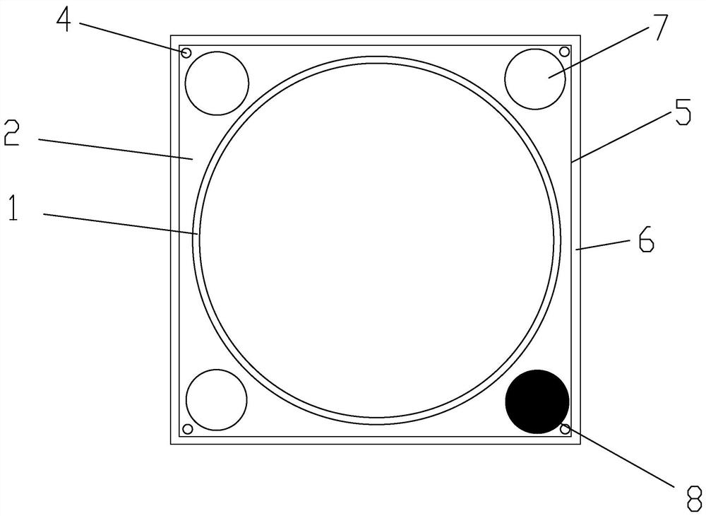
[0045] exist figure 1 , figure 2 In the illustrated embodiment, a residential compound exhaust duct includes:

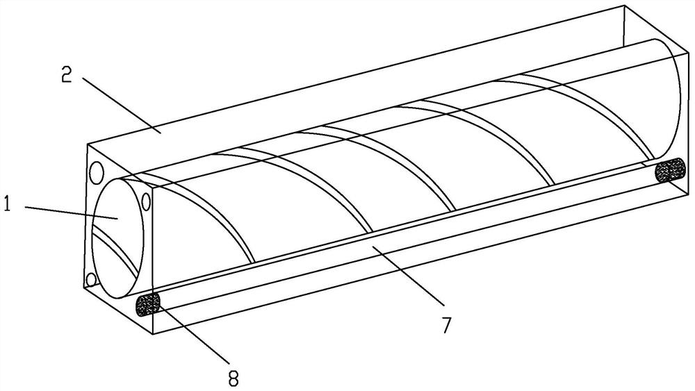
[0046] The inner exhaust channel 1 is used for the internal passage of oil fume gas. The inner exhaust channel 1 is a metal pipe; the inner exhaust channel 1 is a stainless steel spiral pipe body; the inner exhaust channel 1 is circular airway;

[0047] The outer exhaust duct 2 is arranged outside the inner exhaust duct 1 to fix and form the outer cladding of the composite exhaust duct. The outer exhaust duct 2 is a lightweight concrete pipe; the outer exhaust duct 2 is a lightweight concrete pipe. Concrete pouring square pipe body; the two ends of the outer exhaust duct 2 are provided with diameter-reducing structures 19; also include,

[0048] Reinforcement 3, a member arranged on the outer exhaust duct 2 to strengthen the strength and integrity of the inner exhaust duct 1 and the outer exhaust duct 2;

[0049] Wherein, the outer exhaust duct 2 is integrally p...


PUM


Abstract

The invention discloses a residence composite exhaust passage. The residence composite exhaust passage comprises an inner exhaust passage, an outer exhaust passage and a reinforcing part, wherein the inner exhaust passage is an inner passage used for exhausting oil smoke gas, the inner exhaust passage is a metal pipeline, the outer exhaust passage is arranged outside the inner exhaust passage and used for fixing and forming an outer coating body of the composite exhaust passage, the outer exhaust passage is a lightweight concrete pipeline, the reinforcing part is arranged on the outer exhaust passage and is used for reinforcing the strength and integrity of the inner exhaust passage and the outer exhaust passage, and the outer exhaust passage is integrally poured outside the inner exhaust passage, and the outer exhaust passage and the inner exhaust passage form the integrated composite exhaust passage. The invention further discloses a mounting method of the residence composite exhaust passage. According to the residence composite exhaust passage, the metal pipeline is adopted as the inner exhaust passage, the sealing performance is good, the smoke leakage phenomenon is avoided, the lightweight concrete pipeline is adopted outside, cost saving is facilitated, installation is convenient, and the connecting and sealing effects are good; and according to the composite exhaust passage made of different materials inside and outside, seamless butt joint between layers is achieved, the sealing effect is good, and the smoke leakage phenomenon is avoided.

Description

technical field [0001] The invention relates to the technical field of fire prevention check valves, in particular to a residential compound exhaust duct and an installation method thereof. Background technique [0002] Existing residential exhaust duct systems are prone to deformation, twisting, and deep bending during long-term use, resulting in smoke leakage due to deformation, twisting, or deep bending of the exhaust duct. Ubiquitous phenomenon; and because most of the existing exhaust ducts use concrete structures, the vertical bearing capacity is limited by the concrete structure during use, which has certain limitations, and the existing exhaust ducts are between floors. There will be a certain connection gap between them, the sealing effect is poor, there will be smoke leakage during use, and the gap will also affect the appearance of the outside. At the same time, the installation of the existing exhaust duct is also extremely inconvenient. [0003] Chinese patent...

Claims


Application Information

Patent Timeline
IPC IPC(8): E04F17/02
CPCE04F17/02E04F17/023
Inventor 范国兴
Owner 杭州润泉环境科技有限公司
Why Eureka
Try Eureka