
Automatic efficient crude oil impurity removal equipment

A technology of crude oil and equipment, which is applied in the field of automatic and efficient crude oil impurity removal equipment, and can solve problems such as waste of crude oil

Inactive Publication Date: 2021-05-04
蔡文强
View PDF6 Cites 0 Cited by
  • Summary
  • Abstract
  • Description
  • Claims
  • Application Information

AI Technical Summary

Problems solved by technology

[0003] When crude oil is extracted from the ground, it will be mixed with a large amount of insoluble impurities such as sediment, and these impurities are generally relatively small. When cleaning, it needs to be filtered and removed with a filter. When using a filter in the traditional cleaning method, the filter is placed If the crude oil does not move, it will be filtered by the crude oil falling by itself. Although this method has the effect of filtering, but because the crude oil itself is viscous, it is difficult to separate the crude oil from the fine impurities by the immovable filter, so part of the crude oil is viscous. Attached to impurities or filter nets, resulting in the waste of some crude oil

Method used


Image

  • Automatic efficient crude oil impurity removal equipment
  • Automatic efficient crude oil impurity removal equipment
  • Automatic efficient crude oil impurity removal equipment

Examples


Embodiment 1

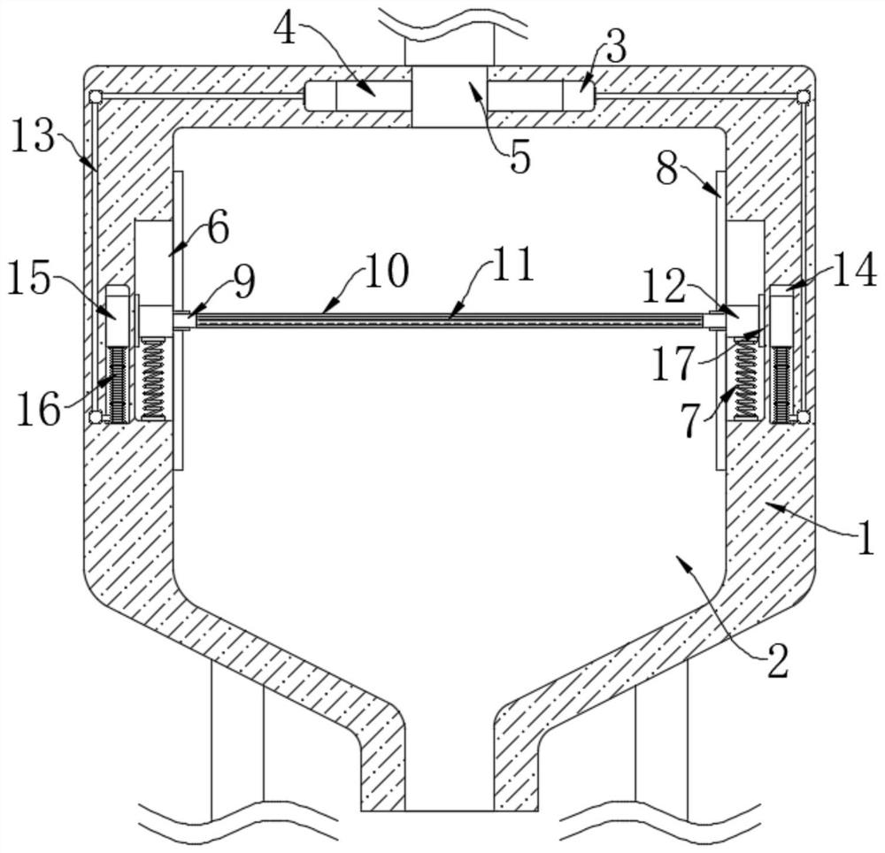
[0020] refer to figure 1 , an automatic high-efficiency crude oil removal equipment, including a housing 1, the housing 1 is a filter box in actual use, a filter chamber 2 is opened in the housing 1, the inner bottom of the filter chamber 2 communicates with the outside world, and the filter chamber 2 The inner bottom is a curved surface, which is convenient for crude oil to flow out of the filter chamber 2. The lower end of the housing 1 is fixedly connected to the ground through a plurality of support rods. An oil inlet pipe is arranged on the top of the housing 1. The oil inlet pipe communicates with the oil inlet 5. When in use, the The oil inlet pipe can be connected with the oil inlet pipe;

[0021] The shaking mechanism, the shaking mechanism includes two shaking grooves 6 symmetrically opened on the inner wall of the filter chamber 2 sides, the two shaking grooves 6 are provided with sliding blocks 12, and the front and rear sides of the two sliding blocks 12 are respe...

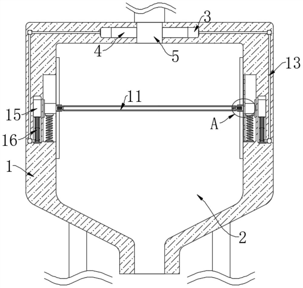
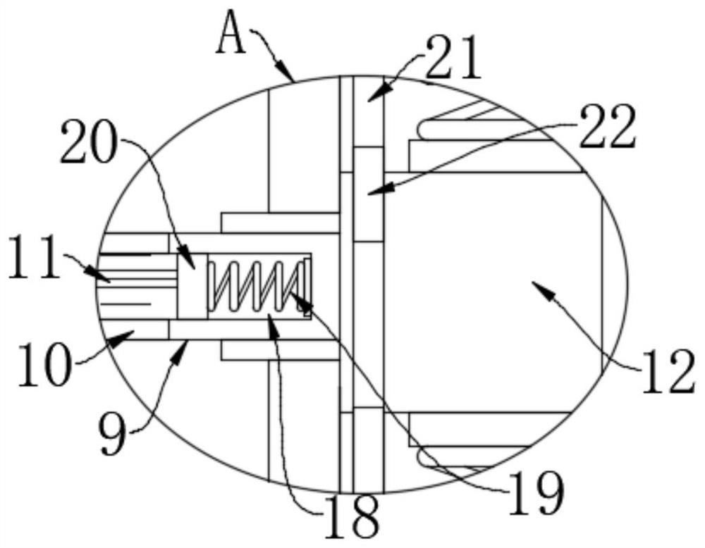
Embodiment 2

[0026] refer to Figure 2-3The difference between this embodiment and Embodiment 1 is that both sides of the opening 10 are provided with sloshing grooves 18, and the two sloshing grooves 18 are all provided with a third magnetic block 20, and the two third magnetic blocks 20 are all connected with each other. Corresponding to the inwall sliding connection of the shaking groove 18, two third magnetic blocks 20 are elastically connected to the inner wall of the shaking groove 18 by the second spring 19 near the side of the shaking groove 6, and the two third magnetic blocks 20 are far away from the side of the shaking groove 6. One side is fixedly connected with the both sides of filter screen 11 respectively, and vertically is provided with guide rod 21 in one of shaking groove 6, and guide rod 21 runs through corresponding first magnetic block 17, and the two ends of guide rod 21 are connected with corresponding shaking groove 6 respectively. The inner top and inner bottom of...


PUM


Abstract

The invention discloses automatic efficient crude oil impurity removal equipment which comprises a shell and a shaking mechanism.A filter chamber is formed in the shell, the inner bottom of the filter chamber is communicated with the outside, and the lower end of the shell is fixedly connected with the ground through a plurality of supporting rods. And the shaking mechanism comprises two shaking grooves symmetrically formed in the inner walls of the two sides of the filtering chamber, sliding blocks are arranged in the two shaking grooves, and the front sides and the rear sides of the two sliding blocks are slidably connected with the inner walls of the corresponding shaking grooves correspondingly. When the equipment is used, fine impurities in crude oil are filtered through the filter screen, and the filter screen is shaken up and down and left and right in the filtering process, so that waste caused by the fact that part of the crude oil is adhered to the impurities or the filter screen is avoided.

Description

technical field [0001] The invention relates to the technical field of oil refining and chemical industry, in particular to an automatic and efficient crude oil impurity removal equipment. Background technique [0002] Oil refining is a process in which crude oil or other oils are distilled without changing the molecular structure. In the process of oil refining, crude oil must go through a series of processes to obtain various useful petroleum products. It generally refers to oil refining. , that is to crack crude oil into kerosene, gasoline, diesel, heavy oil and other fuels suitable for internal combustion engines, and the impurities in the crude oil need to be filtered before crude oil refining, otherwise the impurities will affect the refining of crude oil; [0003] When crude oil is extracted from the ground, it will be mixed with a large amount of insoluble impurities such as sediment, and these impurities are generally relatively small. When cleaning, it needs to be ...

Claims


Application Information

Patent Timeline
Patent Type & Authority Applications(China)
IPC IPC(8): B01D33/01B01D33/80C10G31/09
CPCB01D33/015B01D33/801C10G31/09B01D2201/4069
Inventor 蔡文强
Owner 蔡文强
Learn More