
Test tool and detection equipment

A technology for testing tooling and workpieces. It is used in earphone/earphone accessories, electrical components and other directions. It can solve problems such as difficulty in ensuring accuracy, product shape error, and difficulty in ensuring pressure to slide products, and achieve the effect of ensuring test accuracy.

Active Publication Date: 2021-04-30
GEER TECH CO LTD
View PDF8 Cites 2 Cited by
  • Summary
  • Abstract
  • Description
  • Claims
  • Application Information

AI Technical Summary

Problems solved by technology

However, pressing the FPC sensing range of the ear sensor with a constant pressure and sliding at a constant speed is easily affected by many factors such as the position of the product and the shape error of the product.
[0003] In the related technology, the detection equipment is susceptible to product pick-and-place errors and product shape errors, so it is difficult to ensure that the product is slid with a constant pressure
At the same time, the real-time feedback of the pressure sensor is used to control the movement of the electric cylinder to ensure a constant pressure to slide the product. It will be affected by many factors such as the feedback lag of the pressure sensor and the correspondence between the change of the pressure sensor and the displacement change of the electric cylinder. It is also difficult to predict. Guaranteed to slide the product with constant pressure, even if it can be achieved, the accuracy is difficult to guarantee

Method used


Image

  • Test tool and detection equipment
  • Test tool and detection equipment
  • Test tool and detection equipment

Examples


Embodiment Construction

[0048] The following will clearly and completely describe the technical solutions in the embodiments of the present invention with reference to the accompanying drawings in the embodiments of the present invention. Obviously, the described embodiments are only part of the embodiments of the present invention, not all of them. Based on the embodiments of the present invention, all other embodiments obtained by persons of ordinary skill in the art without creative efforts fall within the protection scope of the present invention.

[0049] It should be noted that all directional indications (such as up, down, left, right, front, back...) in the embodiments of the present invention are only used to explain the relationship between the components in a certain posture (as shown in the accompanying drawings). Relative positional relationship, movement conditions, etc., if the specific posture changes, the directional indication will also change accordingly.

[0050] At the same time,...


PUM


Abstract

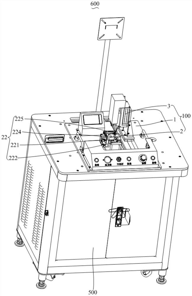
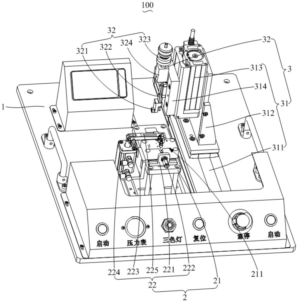
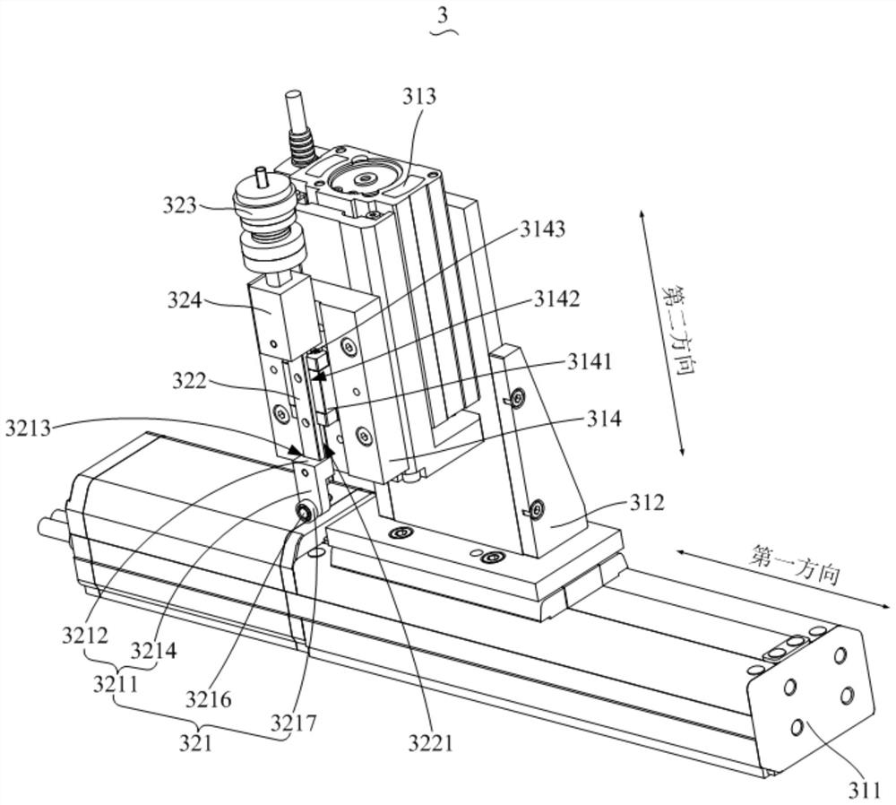
The invention discloses a test tool and detection equipment. The test tool comprises a base, a fixing structure and a test module, wherein the fixing structure comprises a fixing base and a pressing assembly which are arranged on the base, a placement groove is formed in the fixing base, the placement groove is used for placing a workpiece, the pressing assembly is arranged on the fixing base, and the pressing plate is used for pressing the workpiece in the placing groove; and the test module comprises a driving assembly arranged on the base and a pressure assembly movably arranged on the driving assembly, the pressure assembly is provided with a pressing wheel, and the driving assembly drives the pressure assembly to be close to or far away from the workpiece in the placement groove, so that the pressing wheel slides to press the workpiece. The invention aims to provide the test tool which is not influenced by product taking and placing and shape errors and realizes sliding of the product with constant pressure, and the test tool not only ensures sliding of the product with constant pressure, but also ensures test precision.

Description

technical field [0001] The invention relates to the technical field of earphone pressure-sensitivity testing equipment, in particular to a testing tool and testing equipment using the testing tool. Background technique [0002] During the headphone pressure test, it is necessary to press the FPC sensing range of the headphone with a constant pressure and slide at a constant speed. If you only press the earphone with a constant pressure, the FPC sensing range can be guaranteed by controlling the movement of the electric cylinder through the feedback of the pressure sensor. However, pressing the FPC sensing range of the ear sensor with a constant pressure and sliding at a constant speed is easily affected by many factors such as the position of the product and the shape error of the product. [0003] In the related art, the detection equipment is susceptible to product pick-and-place errors and product shape errors, so it is difficult to ensure a constant pressure to slide th...

Claims


Application Information

Patent Timeline
Patent Type & Authority Applications(China)
IPC IPC(8): H04R29/00H04R1/10
CPCH04R29/00H04R1/10
Inventor 程朋昌景凯凯王吉伦刘群丁永胜魏云峰
Owner GEER TECH CO LTD
Learn More