Drill site tracking monitoring method and device

A technology for tracking monitoring and drilling field, applied in the field of drilling, which can solve problems such as low operation efficiency

Active Publication Date: 2021-04-30
山西海平面智能科技有限公司
View PDF9 Cites 1 Cited by
  • Summary
  • Abstract
  • Description
  • Claims
  • Application Information

AI Technical Summary

Problems solved by technology

On the other hand, the existing technology center can only realize fixed-point monitoring for the monitoring of the drilling process. If the working surface is changed, the monitoring angle needs to be readjusted
Therefore, it is urgent to solve the problem of low operational efficiency due to drilling positioning and fixed-point monitoring

Method used


Image

  • Drill site tracking monitoring method and device
  • Drill site tracking monitoring method and device
  • Drill site tracking monitoring method and device

Examples


Embodiment 1

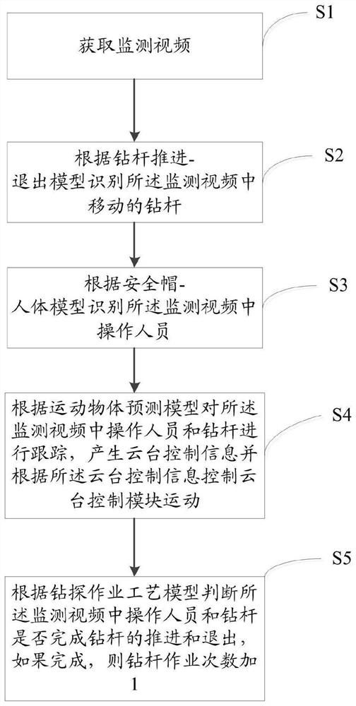
[0045] figure 1 It is the flow chart of the drilling site tracking and monitoring method in Embodiment 1 of the present invention, such as figure 1 As shown, the drilling site tracking monitoring method includes:

[0046] S1: Obtain monitoring video.

[0047] S2: Identify the moving drill pipe in the monitoring video according to the drill pipe advance-exit model.

[0048] S3: Identify the operator in the monitoring video according to the helmet-mannequin.

[0049] S4: Track the operator and the drill pipe in the monitoring video according to the moving object prediction model, generate pan-tilt control information, and control the movement of the pan-tilt control module 3 according to the pan-tilt control information.

[0050] S5: According to the drilling operation process model, it is judged whether the operator and the drill pipe in the monitoring video have completed the advancement and withdrawal of the drill pipe. If completed, the number of drill pipe operations is ...

Embodiment 2

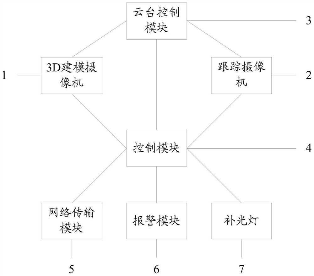
[0053] figure 2 It is a structural block diagram of the drilling site tracking and monitoring device in Embodiment 2 of the present invention, as figure 2As shown, the drilling site tracking and monitoring device includes: a 3D modeling camera 1 , a tracking camera 2 , a pan-tilt control module 3 and a control module 4 . The cloud platform control module 3 is connected with the tracking camera 2 and the 3D modeling camera 1 respectively, and the control module 4 is connected with the cloud platform control module 3, the 3D modeling camera 1 and the tracking camera 1 respectively. Camera 2 is connected. The 3D modeling camera 1 is used to monitor the operation face to be drilled and generate a 3D video. The tracking camera 2 is used for real-time tracking and monitoring of operators and drill pipes to generate monitoring videos. The pan-tilt control module 3 is used to drive the tracking camera 2 and the 3D modeling camera 1 to move. The control module is configured to ex...


PUM


Abstract

The invention discloses a drill site tracking monitoring method and device. The method comprises: firstly, acquiring a monitoring video; secondly, identifying the drill rod moving in the monitoring video according to a drill rod advancing and retreating model; identifying an operator in the monitoring video according to a safety helmet-human body model; tracking an operator and a drill rod in the monitoring video according to a moving object prediction model, generating holder control information, and controlling a holder control module to move according to the holder control information; and finally, judging whether the operator and the drill rod in the monitoring video finish advancing and retreating of the drill rod or not according to a drilling operation process model, and if so, adding 1 to the operation frequency of the drill rod. Tracking monitoring of the drilling machine operation process and counting of the number of times of drilling rod operation are achieved, and the drilling efficiency is improved.

Description

technical field [0001] The invention relates to the technical field of drilling, in particular to a drilling site tracking and monitoring method and device. Background technique [0002] The drilling field is a place where some drilling holes are arranged. During the drilling process, the position of the drilling hole needs to be accurately positioned. In the prior art, an altimeter or a sensor is generally used to detect the position of the drill bit for positioning, which requires precise coordination. Then the workpiece is moved directly under the drill bit to achieve precise positioning. On the other hand, the existing technology center can only realize fixed-point monitoring for the monitoring of the drilling process. If the working surface is changed, the monitoring angle needs to be readjusted. Therefore, it is urgent to solve the problem of low operational efficiency due to drilling positioning and fixed-point monitoring. Contents of the invention [0003] The ob...

Claims


Application Information

Patent Timeline
Patent Type & Authority Applications(China)
IPC IPC(8): H04N7/18H04N13/204H04N13/275H04N13/296H04N5/235H04N5/232G06T7/20
CPCH04N7/18H04N13/204H04N13/275H04N13/296G06T7/20G06T2207/10016G06T2207/20081G06T2207/30204G06T2207/30242H04N23/74H04N23/695
Inventor 张跃国王艳超韦瑜刘宏刚马谦李卫伟车海红李晓宁张文斌
Owner 山西海平面智能科技有限公司
Why Eureka
Try Eureka