
Method and structure for improving isolation of C-band radar antenna under protective material

A technology of protective materials and radar antennas, applied in antennas, antenna couplings, antenna components, etc., can solve problems affecting electromagnetic compatibility, radar mutual interference, and low antenna isolation

Active Publication Date: 2021-04-30
BEIJING INST OF RADIO METROLOGY & MEASUREMENT
View PDF5 Cites 0 Cited by
  • Summary
  • Abstract
  • Description
  • Claims
  • Application Information

AI Technical Summary

Problems solved by technology

[0003] The purpose of the present invention is to provide a method and structure for improving the isolation of the C-band radar antenna under the protective material, so as to solve the problem that the low isolation of the C-band radar antenna under the protective material interferes with each other and affects the electromagnetic compatibility.

Method used


Image

  • Method and structure for improving isolation of C-band radar antenna under protective material
  • Method and structure for improving isolation of C-band radar antenna under protective material

Examples


Embodiment Construction

[0024] The present invention will be described in further detail below in conjunction with the accompanying drawings and specific embodiments. According to the following description and claims, the advantages and features of the present invention will be more clear. It should be noted that all the drawings are in very simplified form and inaccurate scales, and are only used to facilitate and clearly assist the purpose of illustrating the embodiments of the present invention.

[0025] It should be noted that, in order to clearly illustrate the content of the present invention, the present invention specifically cites multiple embodiments to further explain different implementation modes of the present invention, wherein the multiple embodiments are enumerated rather than exhaustive. In addition, for the sake of brevity of description, the content mentioned in the previous embodiment is often omitted in the latter embodiment, therefore, the content not mentioned in the later embo...


PUM


Abstract

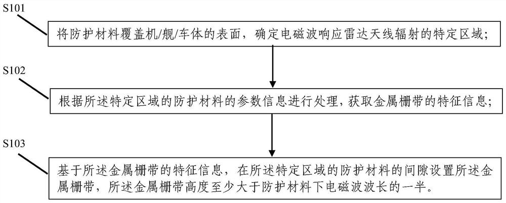
The invention discloses a method and a structure for improving isolation of a C-band radar antenna under a protective material. The method comprises the following steps: enabling the protective material to cover the surface of an aircraft / ship / vehicle body, and determining a specific region of electromagnetic waves responding to the radiation of the radar antenna; processing according to the parameter information of the protective material in the specific area to obtain feature information of a metal grid band; and based on the characteristic information of the metal grid band, arranging the metal grid band in the gap of the protective material in the specific area, wherein the height of the metal grid band is at least greater than half of the wavelength of the electromagnetic wave under the protective material. The method and the structure are simple to implement, coupling energy between the transmitting and receiving antennas can be reduced, transmitting and receiving isolation is improved, and the problem that radar work is affected by electromagnetic interference caused by protective materials is effectively solved.

Description

technical field [0001] The invention belongs to the technical field of radar antennas, in particular to a method and structure for improving the isolation of C-band radar antennas under protective materials. Background technique [0002] Systems such as aircraft, ships, and automobiles usually have multiple radar devices, and these devices must meet electromagnetic compatibility requirements and work normally without mutual interference. For some special applications, protective materials need to be added to the surface of aircraft, ships, and automobiles. One of the protective materials is likely to cause distortion of the antenna pattern, increase the level of the side lobe, and increase the interference signal to the surrounding equipment. Both, the protective material changes the surface current distribution of the aircraft / ship / vehicle body, which will guide the radiated energy into other antennas in the form of surface waves, increasing the coupling energy between ant...

Claims


Application Information

Patent Timeline
Patent Type & Authority Applications(China)
IPC IPC(8): H01Q1/52H01Q1/32H01Q1/34H01Q1/28
CPCH01Q1/525H01Q1/3233H01Q1/34H01Q1/285H01Q1/28
Inventor 代明珍齐万泉黄承祖刘星汛
Owner BEIJING INST OF RADIO METROLOGY & MEASUREMENT
Learn More