
Sensor measuring point position determining method and device

A technology of measuring point location and determination method, which is applied in the direction of measuring devices, instruments, special data processing applications, etc., can solve the problem of sensor configuration redundancy and achieve the effect of avoiding redundancy

Pending Publication Date: 2021-04-30
DONGFENG MOTOR CORP HUBEI
View PDF3 Cites 1 Cited by
  • Summary
  • Abstract
  • Description
  • Claims
  • Application Information

AI Technical Summary

Problems solved by technology

[0003] The embodiment of the present application provides a method and device for determining the location of sensor measuring points to solve the problem that in the prior art, when the modal kinetic energy method is used for optimal arrangement, two similar measuring points are usually selected at the same time. Issues that lead to redundant sensor configurations

Method used


Image

  • Sensor measuring point position determining method and device
  • Sensor measuring point position determining method and device
  • Sensor measuring point position determining method and device

Examples


Embodiment Construction

[0053]The embodiments will be described in detail hereinafter, examples of which are illustrated in the accompanying drawings. When the following description refers to the accompanying drawings, the same numerals in different drawings refer to the same or similar elements unless otherwise indicated. The implementations described in the following examples do not represent all implementations consistent with the examples of the present application. These are merely examples of systems and methods consistent with aspects of the embodiments of the present application as recited in the claims.

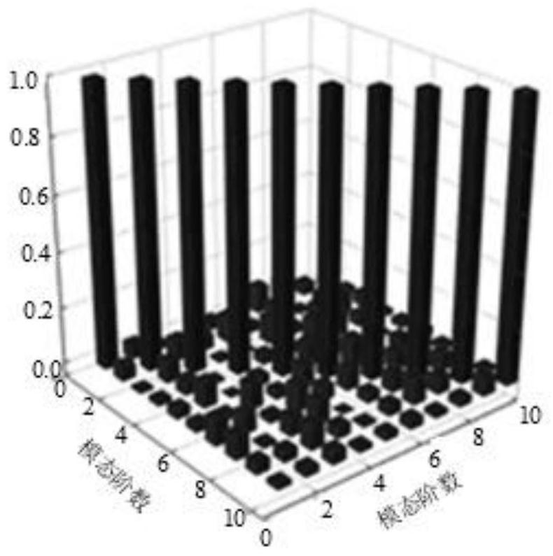
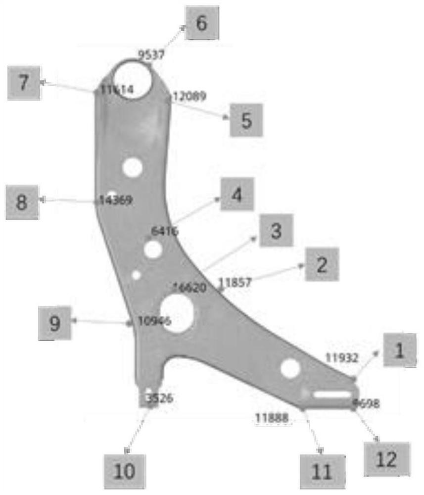
[0054] see figure 1 , figure 1 It is a flow chart of a method for determining the position of a sensor measuring point provided in an embodiment of the present application. Such as figure 1 shown, including the following steps:

[0055] Step 101, obtaining the strain mode matrix of the multi-order modes.

[0056] In step 101, the strain mode matrix of multi-order modes can be obtained...


PUM


Abstract

The embodiment of the invention discloses a sensor measuring point position determination method and device. The method comprises the steps of acquiring a strain modal matrix of a multi-order modal; determining a Fischer information matrix according to the strain modal matrix; calculating a value of a determinant of the Fischer information matrix; and when the value of the determinant of the Fischer information matrix is determined to be the maximum value, indicating that the position of the target node identified in each order of modality in the multi-order modalities is the measuring point position of the sensor, wherein the target node is the node with the maximum modal strain energy in the plurality of nodes included in the order of modalities. Thus, when the value of the determinant of the Fischer information matrix is determined to be the maximum value, the position of the target node identified in each order of modality in the multi-order modalities is the measuring point position of the sensor, and redundancy of sensor configuration is avoided.

Description

technical field [0001] The embodiments of the present application relate to the technical field of durability testing of metal structural parts, and in particular to a method and device for determining the position of a sensor measuring point. Background technique [0002] At present, the optimal arrangement methods of strain sensors for metal structural parts include modal kinetic energy method, effective independence method and modal confidence criterion method, etc. Among them, the more commonly used methods include the modal kinetic energy method and the effective independence method. For the modal kinetic energy method, in order to establish a more accurate finite element model for structural parts such as the triangle arm of a car, it is required to divide a very large number of discrete meshes, sometimes even reaching tens of thousands. Due to the dense distribution of measuring points, when the modal kinetic energy method is used to optimize the layout, two similar ...

Claims


Application Information

Patent Timeline
Patent Type & Authority Applications(China)
IPC IPC(8): G06F30/18G06F30/23G01B21/00G01B21/32
CPCG06F30/18G06F30/23G01B21/00G01B21/32
Inventor 刘汉文陈海滨李衡何洋潘子安
Owner DONGFENG MOTOR CORP HUBEI
Learn More