
A case side panel locking system and locking method thereof

A side panel and chassis technology, applied in the direction of instruments, transportation and packaging, digital data processing components, etc., can solve the problems of cumbersome operation and slow disassembly of computer chassis, so as to improve product quality, enhance customer experience, and improve use The effect of longevity

Active Publication Date: 2022-07-12
INSPUR SUZHOU INTELLIGENT TECH CO LTD
View PDF4 Cites 0 Cited by
  • Summary
  • Abstract
  • Description
  • Claims
  • Application Information

AI Technical Summary

Problems solved by technology

[0004] The present invention mainly solves the problem that the traditional computer case needs to be screwed to disassemble the cover plate of the computer case to install the computer accessories.

Method used


Image

  • A case side panel locking system and locking method thereof
  • A case side panel locking system and locking method thereof
  • A case side panel locking system and locking method thereof

Examples


Embodiment 1

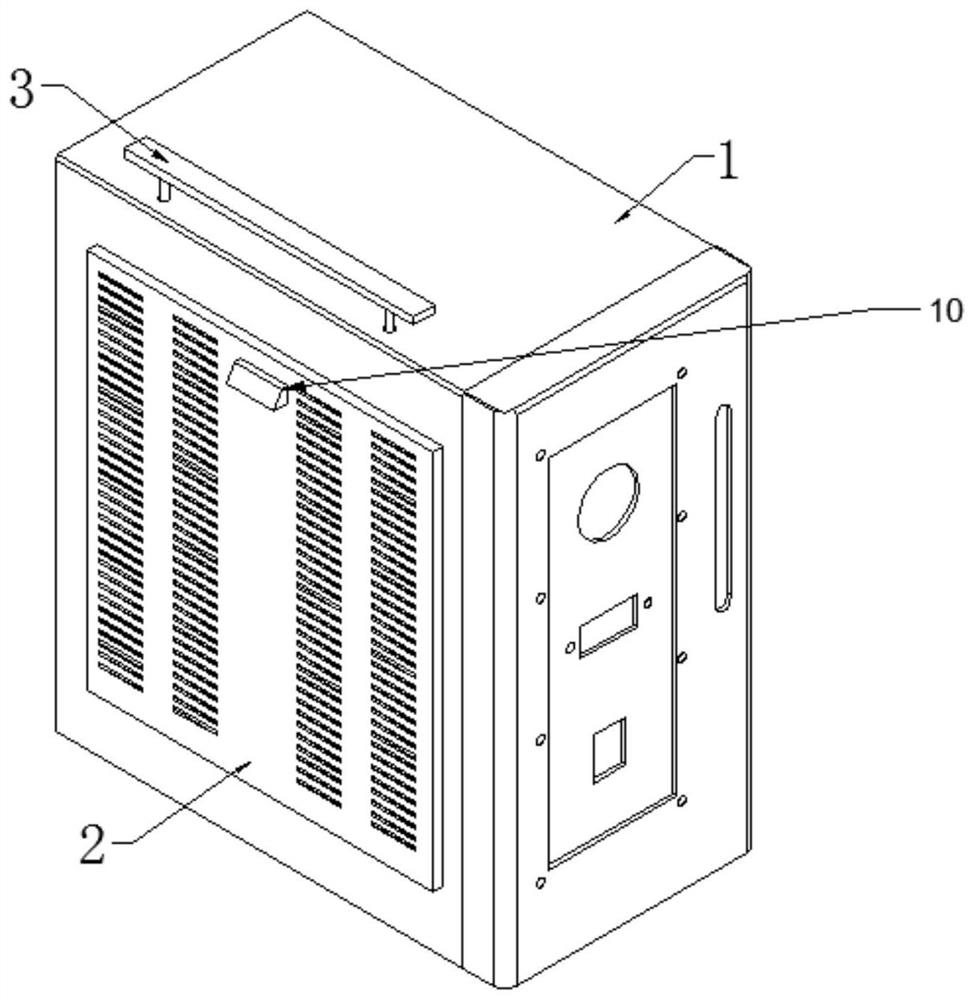
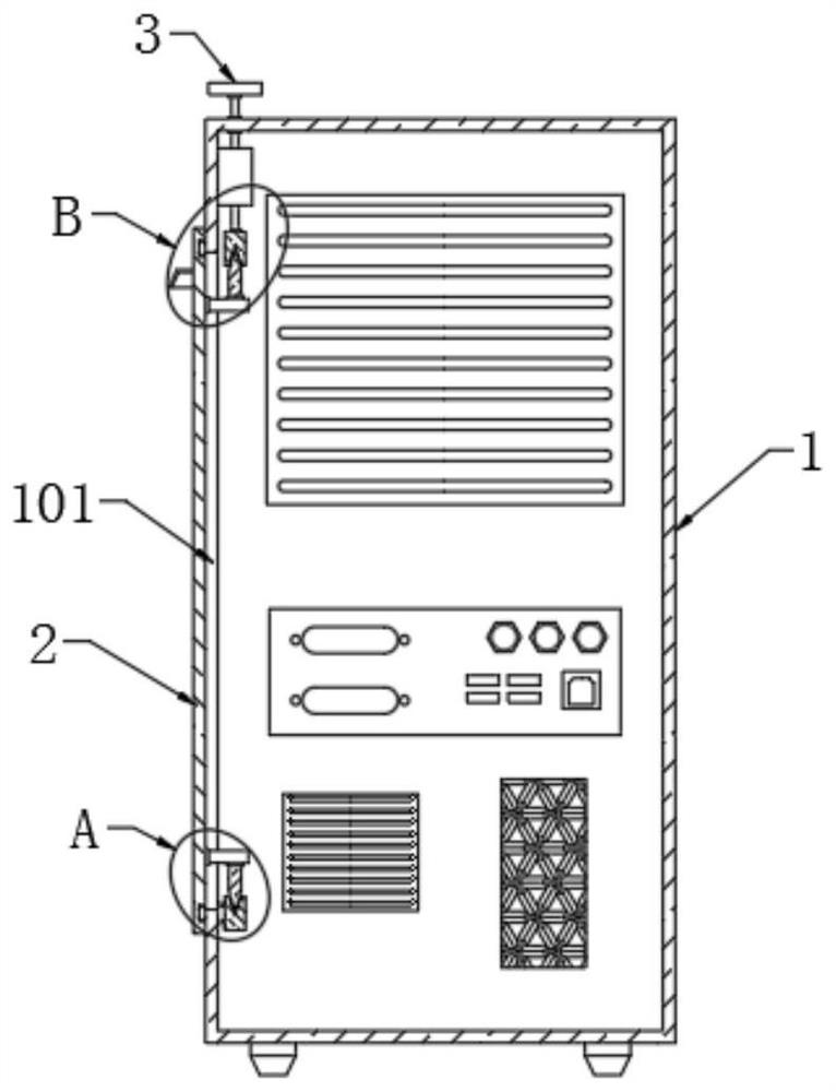
[0042] see Figure 1 to Figure 7 , the embodiment of the present invention provides a chassis side panel locking system, including: a chassis 1, a side panel 2 and a locking mechanism;

[0043] The locking mechanism includes a control module 3 and a limit module;

[0044] One end of the side plate 2 is detachably connected to the chassis 1 through the limit module, and the other end of the side plate 2 realizes the opening and closing action of the side plate 2 on the chassis 1 through the control module 3;

[0045] The limit module includes a first limit module and a second limit module;

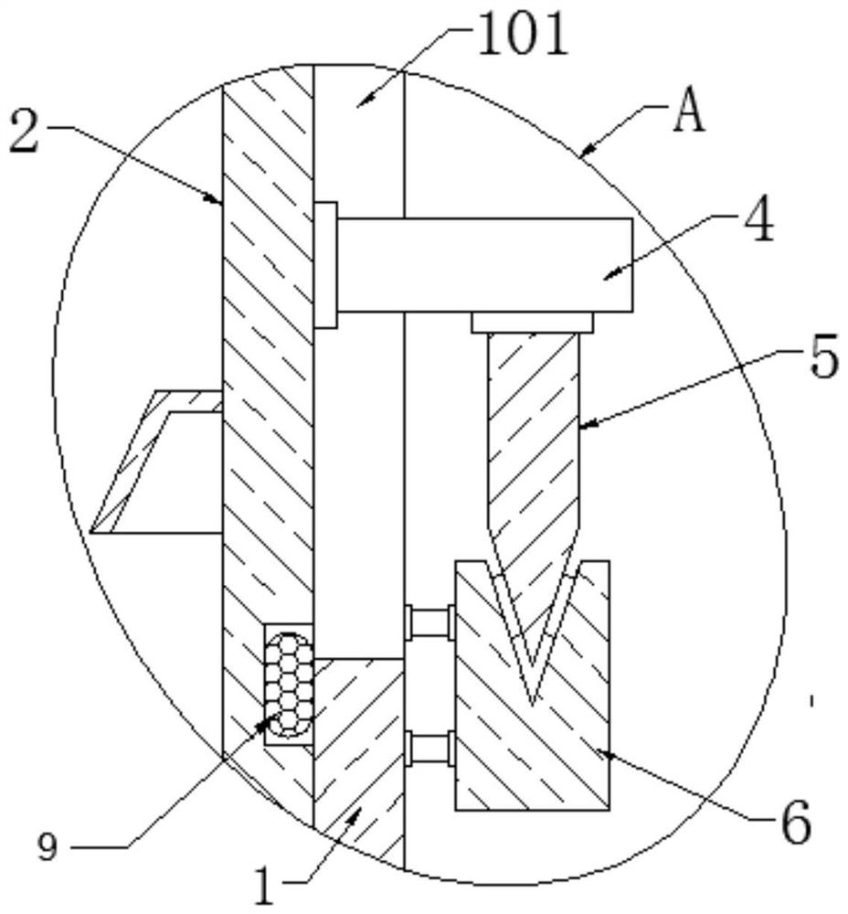
[0046] see figure 2 , a side panel 2 is provided on the side of the chassis 1, a control module 3 is provided above the chassis 1 near the side panel 2, a rectangular hole 101 is provided on the side of the side panel 2 in contact with the chassis 1, and the side of the rectangular hole 101 above the side panel 2 is connected to the The position corresponding to the control 3 is provide...

Embodiment 2

[0057] This embodiment also provides a locking method for a chassis side panel locking system, including:

[0058] Take-out operation: when the side panel 2 is removed from the chassis 1, press the handle 305 downward, the handle 305 drives the pressure rod 305 to move downward, the pressure rod 304 presses the telescopic module 102 downward, and the telescopic module 102 drives the pull rod 302 to move upward, thereby Drive the second block 8 to move upward, separate the second block 8 from the second wedge block 7, so that the top of the side plate 2 is separated from the chassis 1, hold the concave handle to pull the side plate 2 upward, and make the first block The block 6 is separated from the first wedge-shaped block 5 to separate the side panel 2 from the main chassis body 1 , so that the side panel 2 is removed from the chassis 1 .

[0059] When the telescopic module 102 is taken out for work, the handle 305 drives the pressing rod 304 to move down. When the pressing r...


PUM


Abstract

The invention discloses a case side panel locking system, comprising a case, a side panel and a locking mechanism. The side panel is arranged on one side of the case through the locking mechanism; the locking mechanism includes a control module and a limit module; The limit module is detachably connected to the chassis, and the other end of the side plate realizes the opening and closing action with the chassis through the control module; the control module includes a lock block, a lock tongue, a telescopic mechanism and a handle; the telescopic mechanism is fixed on the chassis and close to the side plate The handle and the lock tongue are respectively connected to the two ends of the telescopic mechanism, and the lock block is fixed at the position corresponding to the lock tongue on the side plate; through the above method, the present invention can save the tedious action of screw locking, and just press the upper handle of the case. Bounce the clamping block of the main body of the chassis, and the wedge-shaped block of the side panel is disengaged, and then the side panel of the chassis can be removed. The side panel can also be installed by the same action. Simplicity and improved customer experience.

Description

technical field [0001] The invention relates to the technical field of computer chassis, in particular to a chassis side panel locking system and a locking method thereof. Background technique [0002] The chassis is a part of the accessories of the desktop computer. Its main function is to place and fix the accessories and play a supporting and protective role. In addition, the desktop chassis plays an important role in shielding electromagnetic radiation. Various switches, indicator lights, etc. on the panel are made of a combination of steel plate and plastic with high hardness, which mainly protects the internal components of the chassis. [0003] However, the side panels of the traditional desktop computer chassis are generally fixed on the chassis by screw locking. Although the fixing effect is good, disassembly is more troublesome, and tools such as screwdrivers are required to disassemble or clean the accessories inside the chassis. When there is dust inside the cas...

Claims


Application Information

Patent Timeline
Patent Type & Authority Patents(China)
IPC IPC(8): G06F1/18
CPCG06F1/181Y02T10/7072
Inventor 张庆坤
Owner INSPUR SUZHOU INTELLIGENT TECH CO LTD
Learn More