
Automatic detection method and device for cold finish extrusion machining of screw shaft

An automatic detection device and automatic detection technology, applied in the direction of measuring devices, optical devices, instruments, etc., can solve the problems of lack of processing and automatic production line technology for quality inspection, and achieve the effects of stabilizing processing quality, reducing costs and improving production efficiency

Pending Publication Date: 2021-04-30
DALIAN DEMAISHI PRECISION TECH CO LTD +1
View PDF9 Cites 0 Cited by
  • Summary
  • Abstract
  • Description
  • Claims
  • Application Information

AI Technical Summary

Problems solved by technology

At present, the hollow screw shaft is only in the processing and development stage, lacking subsequent processing, quality inspection, and integrated automatic production line technology

Method used


Image

  • Automatic detection method and device for cold finish extrusion machining of screw shaft
  • Automatic detection method and device for cold finish extrusion machining of screw shaft
  • Automatic detection method and device for cold finish extrusion machining of screw shaft

Examples


Embodiment Construction

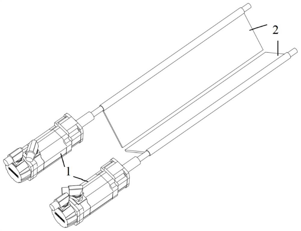
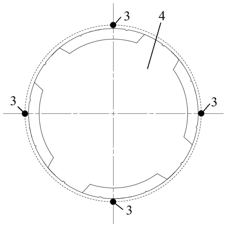
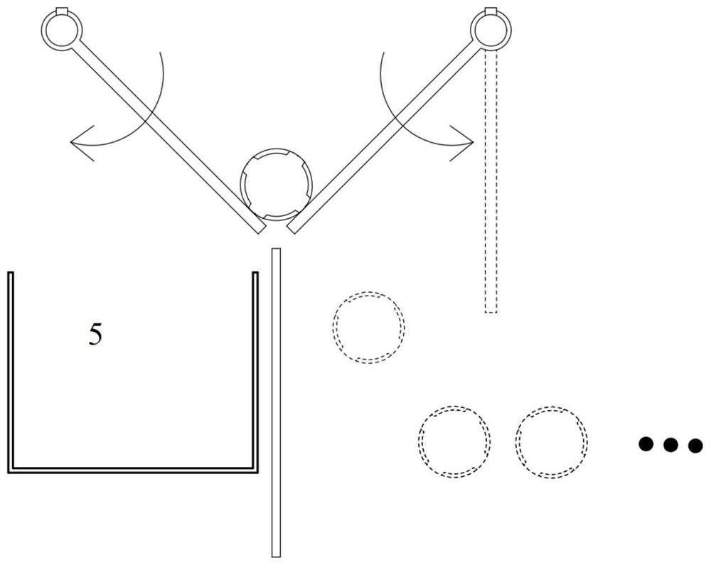
[0028] exist figure 1 and Figure 4 In the schematic diagram of the present invention shown, two servo motors 1 are respectively connected to the corresponding side plates 2, there is a gap between the lower parts of the two side plates, and the two side plates form a V-shaped groove. The rotation angle of the side plates is controlled by the servo motor to ensure that the two side plates can reach the same position after each rotation. The laser beam emitting device 6 and the laser beam receiving device 7 are placed at both ends of the screw shaft. The laser beam emitting device is composed of four uniformly distributed laser beam emitters, and the laser beam receiving device is composed of uniformly distributed four laser beam receivers. The front end of the laser beam receiver of the laser beam receiving device is provided with a nut 8, and the aperture of the central hole of the nut can be smaller than the laser spot diameter of the laser beam receiver of the laser beam ...


PUM


Abstract

The present invention provides an automatic detection method and device for cold finish extrusion machining of a screw shaft, two servo motors are connected with corresponding side plates respectively, a gap is formed between the lower portions of the two side plates, and the two side plates form a V-shaped groove. The rotating angle of the side plates is controlled through the servo motor, and it is guaranteed that the two side plates can reach the same position after rotating each time. The laser beam emitting device and the laser beam receiving device are arranged at the two ends of the screw shaft. The detection method comprises the following steps: (1) conveying the screw shaft; (2) carrying out linear detection on the screw shaft; and (3) conveying the detected screw shaft. The problem of linear detection on a screw shaft production line is solved, the production efficiency can be greatly improved while the stable machining quality is ensured, and the cost is reduced. Quality detection is a necessary procedure for screw shaft machining, and the automation level of quality detection directly influences the overall machining efficiency.

Description

technical field [0001] The invention belongs to the technical field of screw shaft processing, in particular to a method and device for detecting straightness of a screw shaft after precise extrusion processing. Background technique [0002] The brake-by-wire system is derived from the wire-control technology in the aviation field. It has been gradually applied in the automotive field in recent years. It has advantages that cannot be compared with traditional brake control systems, such as simple system structure, short braking response time, high performance and good environment. , Good durability, easy to quickly integrate with other functions, etc. Brake-by-wire system is one of the development directions of automobile technology, and its safety and reliability are the biggest challenges at present. [0003] The brake-by-wire system includes a brake pedal with electronic sensors, a central controller, a brake actuation module, a communication unit, and a power supply. W...

Claims


Application Information

Patent Timeline
IPC IPC(8): G01B11/27
CPCG01B11/27
Inventor 何建平魏兆成刘国龙齐宏福郭明龙
Owner DALIAN DEMAISHI PRECISION TECH CO LTD
Learn More