Eureka AIR delivers breakthrough ideas for toughest innovation challenges, trusted by R&D personnel around the world.

Burner for gas stove

A technology for burners and gas stoves, which is applied in the direction of gas fuel burners, burners, burners, etc. It can solve the problems of incomplete combustion, affecting heat transfer, deformation of the fire cover body, etc., and achieves uniform heating of the bottom of the pot and easy transmission. The effect of fire and air flow

Pending Publication Date: 2021-04-30
NINGBO FOTILE KITCHEN WARE CO LTD
View PDF1 Cites 0 Cited by
  • Summary
  • Abstract
  • Description
  • Claims
  • Application Information

AI Technical Summary

Problems solved by technology

[0002] At present, the fire cover of a gas stove usually includes an inner ring fire cover and an outer ring fire cover, and the heating method for the pot body is basically a combination of an external annular flame and an internal annular flame, and the inner and outer ring fire covers are basically A full circle of fire holes. In this case, the smoke flows from the center to the outer ring. The smoke generated by the combustion of the inner ring must first pass above the fire holes of the outer ring, and then flow outward, resulting in the smoke generated by the combustion of the inner ring. The impact of the outer ring flame, for example, it is easy to cause the outer ring flame not to fit the bottom of the pot, which affects the heat transfer; or the flow of flue gas causes the secondary air to be supplemented smoothly, resulting in incomplete combustion, so it is necessary to develop a new burner structure
In addition, most of the traditional burner fire caps sold on the market are milled with one groove, that is, there is a fire pilot groove milled on the top of the fire cap body. Disconnected, so it is easy to cause deformation of the fire cover body, thus affecting the ignition effect
[0003] For example, the Chinese utility model patent "Gas burner with fire transmission device and flameout protection function" whose patent number is 201220464214.0 (announcement number is CN202813375U) discloses a similar fire transmission structure. Outer ring fire spray hole, and the outer ring fire transmission device is also provided on the outer ring fire spray ring, the outer ring fire transmission device is a boss installed on the inner wall of the outer ring fire spray ring, set on the The outer ring fire transmission hole and the outer ring fire transmission groove on the boss and the outer ring flame spraying ring are composed of the outer ring fire transmission hole and the outer ring fire transmission groove, and the outer ring fire transmission hole and the outer ring fire transmission groove An outer ring fire spray hole is connected to realize rapid fire transmission; the fire transmission groove of this fire transmission structure is open, and the fire transmission is linear, that is, the fire transmission groove is exposed on the surface of the outer ring fire cover. This design has One advantage is that the supply of secondary air in the fire transmission tank is very sufficient. The open fire transmission tank can ensure the supply of secondary air when the flame burns in the fire transmission tank, which is conducive to flame combustion and fire transmission, and has the characteristics of fast fire transmission , but the open fire transfer channel is easy to cause the blockage of the fire transfer channel, that is, the soup flowing down from the bottom of the pot can easily flow into the fire transfer channel, and the blockage will affect the fire transfer performance. This is also the main reason for the blockage and maintenance of the current fire transfer channel
Finally, in order to avoid unfavorable working conditions such as yellow fire and tempering during the use of the burner, most of the existing cookers on the market have a structure with adjustable primary air, but they ignore the fact that there is too much or too little secondary air. It will also affect the combustion state. Therefore, in summary, in addition to the above-mentioned improvements, the existing stove burners still have a lot of room for improvement in terms of anti-blocking performance and cleanliness

Method used


Image

  • Burner for gas stove
  • Burner for gas stove
  • Burner for gas stove

Examples


Embodiment Construction

[0034]The present invention will be further described in detail below with reference to the accompanying drawings embodiments.

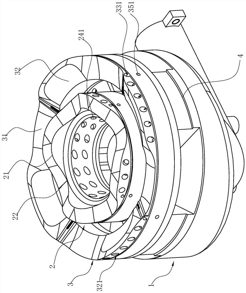
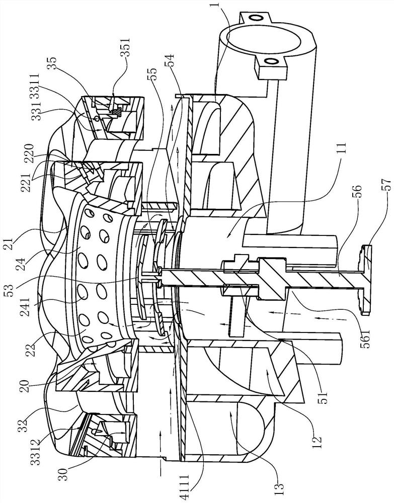
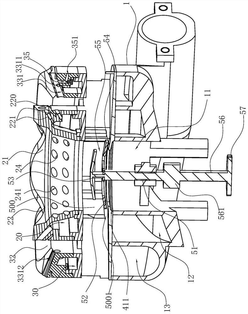
[0035]Such asFigure 1 ~ 9 As shown, it is the best embodiment of the present invention. In this embodiment, the burner for the gas stove includes a base 1, provided above the base 1, has an internal cover 2 having a ignition / aircraft structure, and is also provided above the base 1, provided in the inner The periphery of the fire cover 2, and the ignition / fire structure corresponding to the inner fire cover 2 has an outer fire cover 3 of the fire / ignition structure, wherein the upper surface of the outer fire cover 3 and / or the inner fire cover 2 is partially uneven. The structure and the overall wave-shaped wavy, the ignition / fire structure of the inner fire cover 2 is located in the inner convex portion 21 of its uneven structure, correspondingly, the fire / ignition structure of the outer fire cover 3 is located at its uneven structure. At 31, th...


PUM


Abstract

The invention relates to a burner for a gas stove. The burner comprises a base, an inner burner cap which is arranged on the base and is provided with an ignition / fire transfer structure, and an outer burner cap which is also arranged on the base, is arranged on the periphery of the inner burner cap and is provided with a fire transfer / ignition structure corresponding to the ignition / fire transfer structure of the inner burner cap; the burner is characterized in that the whole outer burner cap and / or the whole inner burner cap are / is in the staggered wave shape, the ignition / fire transfer structure of the inner burner cap is located in the inner convex position of the concave-convex structure of the inner burner cap, and correspondingly, the fire transfer / ignition structure of the outer burner cap is located in the outer concave position of the concave-convex structure of the outer burner cap. Compared with the prior art, the burner has the advantages that the upper surface of the outer burner cap and / or the upper surface of the inner burner cap are / is at least partially provided with the concave-convex structures, and the whole burner is in the staggered wave shape, so that internal airflow and external airflow of the outer burner cap and the inner burner cap are not interfered, and meanwhile, the effect of uniformly heating the bottom of a pot can be achieved; in addition, arrangement of the special position of the fire transfer / ignition structure enables fire transfer to be easier.

Description

Technical field[0001]The present invention relates to the field of home kitchenware, and more particularly to a burner for a gas stove.Background technique[0002]At present, the fire cover of the gas cooker typically includes an inner ring fire cover and an outer ring cover, which is basically a combination of an external annular flame and an internal ring flame in an external annular flame and an internal outer ring cover. A entirety of the fire hole, in this case, the flue gas flows from the center to the outer ring, and the flue gas generated by the inner ring burning will be above the outer ring fire hole, thereby causing the flue gas generated by the inner ring burning. In the influence of the outer ring flame, if the outer ring flame can not be bonded to the bottom of the pot, affect the heat transfer; or the flow of flue gas causes the secondary air to supplement, causing incomplete combustion, therefore needs to develop a new burner structure . In addition, most of the tradit...

Claims


Application Information

Patent Timeline
Patent Type & Authority Applications(China)
IPC IPC(8): F23D14/46F23D14/58F23D14/62F23L9/00F24C3/08F24C3/10F24C3/12F24C15/14
CPCF23D14/46F23D14/58F23D14/62F23D2207/00F23L9/00F24C3/085F24C3/10F24C3/126F24C15/14
Inventor 柯情刘晓刚王帅东叶佳辉
Owner NINGBO FOTILE KITCHEN WARE CO LTD
Why Eureka
Eureka Blog
Learn More