Method for designing, manufacturing and assembling hydrodynamic machines

A technology of hydraulic machines and hydraulic cylinders, which is applied in the field of design, manufacture, and assembly of hydraulic machines, and can solve problems such as environmental pollution

Pending Publication Date: 2021-04-30
焦述理
View PDF0 Cites 0 Cited by
  • Summary
  • Abstract
  • Description
  • Claims
  • Application Information

AI Technical Summary

Problems solved by technology

[0002] Steam engines and internal combustion engines burn fossil fuels and use non-renewable fossil energy, thus causing environmental pollution
People are eager and have been seeking alternatives to renewable and clean energy, hoping to change the way energy is used and protect the natural environment of the earth. However, the goal of getting rid of the use of disposable fossil energy has not been achieved so far.

Method used


Image

  • Method for designing, manufacturing and assembling hydrodynamic machines
  • Method for designing, manufacturing and assembling hydrodynamic machines
  • Method for designing, manufacturing and assembling hydrodynamic machines

Examples


Embodiment Construction

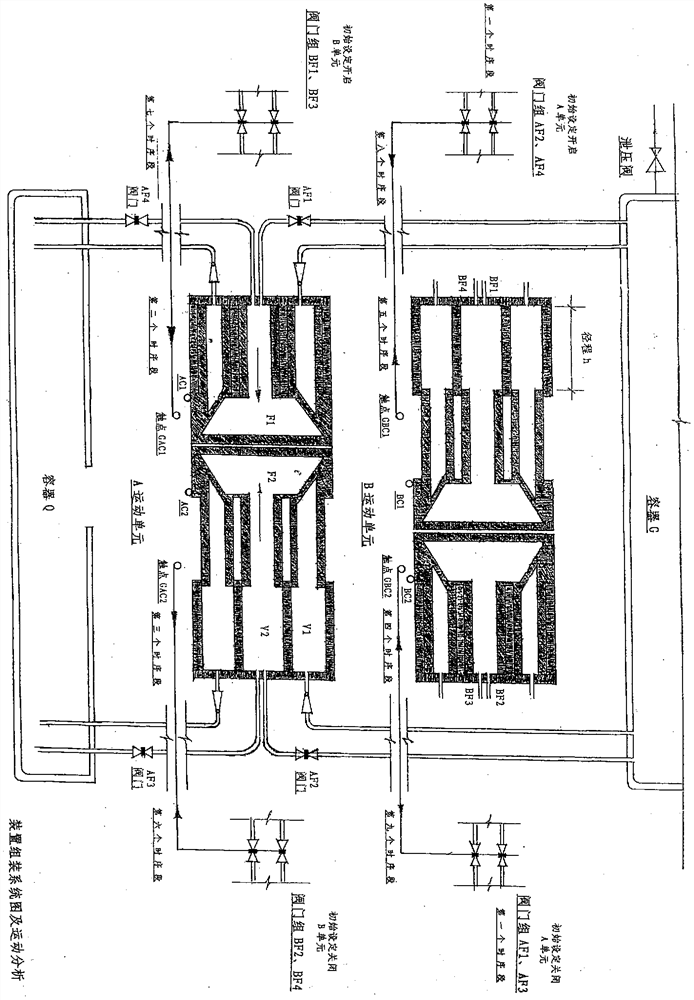
[0063] Such as image 3 As shown, place container G at a high place, container Q at a low place, and fix A and B motion units at appropriate positions; arrange the pipelines of A and B motion units as needed, so that the valves of the pipelines can be arranged in groups , so that it can be connected with the transmission parts and fixed in a suitable position.

[0064] Such as image 3 As shown, the pipeline connection and valve settings of B motion unit are exactly the same as those of A motion unit, so the drawing is omitted.

[0065] Such as image 3 As shown, the pipeline valves of the A and B motion units in the device are arranged in groups, and the valve groups are set as follows: ①AF1, AF3, ②AF2, AF4, ③BF1, BF3, ④BF2, BF4 are coaxial stud valves, and the stud rotates once It can control a group of two valves to open or close at the same time.

[0066] Such as image 3 As shown, the four groups of coaxial stud valve groups are respectively connected to the four lin...


PUM


Abstract

The invention relates to a method for designing, manufacturing, and assembling a set of devices named as hydrodynamic machines. Two containers are arranged in the whole device, one container is located at a high position, the other container is located at a low position, liquid in the container located at the high position generates hydraulic pressure due to self-weight and height difference, the hydraulic pressure is transmitted to core components of the device through a pipeline, and the core components of the device can convert the hydraulic pressure into thrust. Other components of the device enable the core part to continuously change the spatial position and direction by utilizing the thrust converted by the hydraulic pressure through changing the transmission path of the hydraulic pressure. The core components of the device are combined in pairs to form a motion unit, the two core components of the motion unit generate thrust through hydraulic pressure, and the two strands of thrust enable the motion unit of the device to generate continuous, periodic and reciprocating motion. A motion unit A and a motion unit B are arranged in the whole device, the motion unit A and the motion unit B mutually drive valves of hydraulic pipelines of the opposite sides to rotate, control the opening and closing states of the valves, start and brake the motion of the opposite sides and mutually control the motion states of the opposite sides in the motion process, and therefore the device can automatically generate periodic, reciprocating and circulating motion, and power can be output to equipment except the device to generate electric power.

Description

technical field [0001] Fluid machinery, new energy. Background technique [0002] Steam engines and internal combustion engines burn fossil fuels and use non-renewable fossil energy, thus causing environmental pollution. People are eager and have been seeking alternatives to renewable and clean energy, hoping to change the way of energy use and protect the natural environment of the earth. However, the goal of getting rid of the use of disposable fossil energy has not been realized so far. Contents of the invention [0003] Gravity always exists on the earth. In the natural state, objects leaving the ground are always drawn by gravity to move towards the ground. Finally, the objects fall back to the ground or are supported by ground attachments. The gravity is carried by the ground and loses the space for movement, and the movement stops. Can't be used. [0004] In the natural state, the self-weight of the liquid in the container and the height of the drop generate hydra...

Claims


Application Information

Patent Timeline
Patent Type & Authority Applications(China)
IPC IPC(8): F15B11/16F15B13/06F15B15/14F15B15/20F03B13/00
CPCF03B13/00F05B2220/706F15B11/16F15B13/06F15B15/1423F15B15/149
Inventor 焦述理
Owner 焦述理
Why Eureka
Try Eureka