Glass melting furnace masonry robot and method
A glass melting furnace and robot technology, which is applied in the construction, building structure, processing of building materials, etc., to achieve the effect of strong practicability and high degree of automation
- Summary
- Abstract
- Description
- Claims
- Application Information
AI Technical Summary
Problems solved by technology
Method used
Image

Examples
Embodiment 1
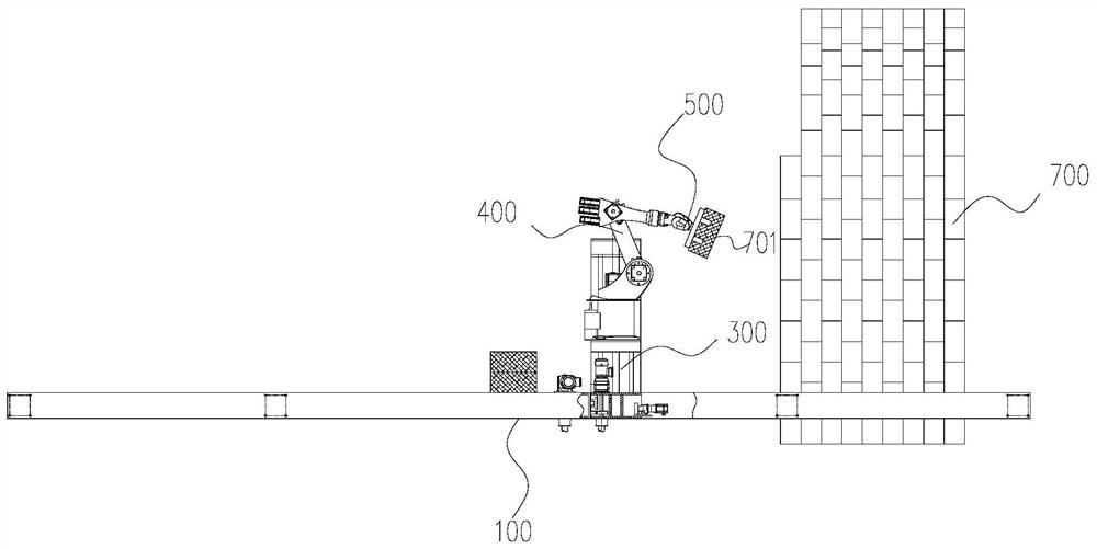
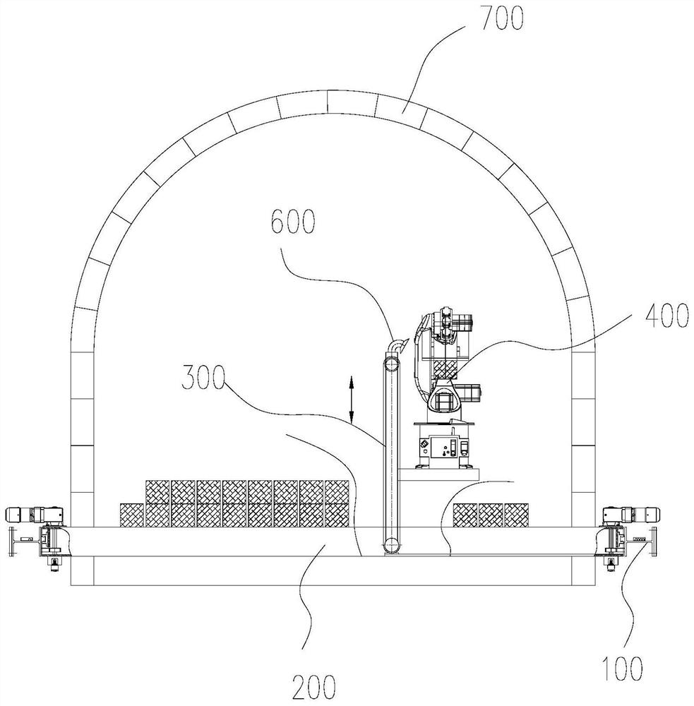
[0056] Such as figure 1 , figure 2 , image 3 As shown, the glass melting furnace masonry robot includes a first base 100, a second base 200, a lifting mechanism 300, a manipulator 400 with six degrees of freedom, a grabbing mechanism 500, a slurry pump assembly 600, and a controller.
[0057] The first base 100 is horizontally arranged on both sides of the melting furnace 700, the second base 200 is slidably connected to the first base 100 on both sides, and the lifting mechanism 300 is slidably connected to the second base 200 Above, the manipulator 400 can be vertically lifted and connected to the lifting mechanism 300, the grasping mechanism 500 can be rotatably connected to the end of the manipulator 400, and the pipeline of the pumping slurry assembly 600 is along the second base 200. , the lifting mechanism 300 is laid, the slurry opening 601 of the pumping slurry assembly 600 is located on the side of the manipulator 400, the controller is connected with the first b...
Embodiment 2
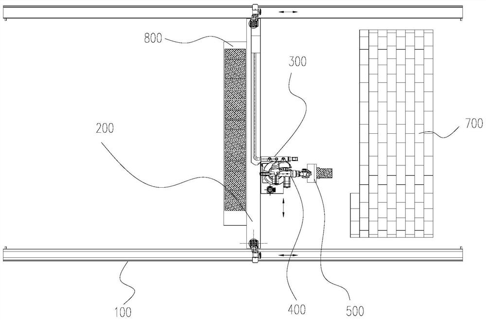
[0071] Such as image 3 As shown, on the basis of the first embodiment above, a brick stacking platform 800 for stacking bricks 701 is further provided on the side of the second base 200 .
[0072] The brick stacking platform 800 can also be provided with a separate horizontal and lateral walking component, which can be realized by other means such as the cooperation of gears and racks, and can independently realize the lateral movement of the brick stacking platform 800, making it more adaptable.
[0073] A certain amount of bricks 701 are reserved on the brick stacking platform 800, and the second base 200 can also drive the bricks 701 to move to a suitable position together, which can realize the integration of brick transportation, plastering and masonry.
[0074] Among them, the second base 200 is also equipped with a hydraulic feeding area to realize the plastering operation of the bricks 701; the drag chain area of the bridge frame arranges all the electrical pipeline...
Embodiment 3
[0077] Such as Figure 5 , Figure 6 shown, and refer to Figure 7 As shown, on the basis of the first embodiment above, the lifting mechanism 300 also includes a portal frame 307, a lifting motor mounting plate 308, a lifting platform 309, and a lifting component. The middle part of the portal frame 307 is empty for installing the lifting component , the lifting motor mounting plate 308 and the second motor mounting plate 301 are arranged in parallel and spaced up and down, and are connected to the portal frame 307, the lifting assembly is connected to the portal frame 307, and the lifting Platform 309 is connected to the lifting assembly.
[0078]Wherein, the lifting assembly includes a lifting motor 310, a driving wheel 311, a driven wheel 312, a wheel belt 313, and a shaft coupling structure 314. The lifting motor 310 is connected to the lifting motor mounting plate 308, and the lifting motor 310 is connected to the Referring to the driving wheel 311, there are two driv...
PUM
| Property | Measurement | Unit |
|---|---|---|
| Rotation angle | aaaaa | aaaaa |
Abstract
Description
Claims
Application Information
 - R&D
- Intellectual Property
- Life Sciences
- Materials
- Tech Scout
- Unparalleled Data Quality
- Higher Quality Content
- 60% Fewer Hallucinations
Browse by: Latest US Patents, China's latest patents, Technical Efficacy Thesaurus, Application Domain, Technology Topic, Popular Technical Reports.
© 2025 PatSnap. All rights reserved.Legal|Privacy policy|Modern Slavery Act Transparency Statement|Sitemap|About US| Contact US: help@patsnap.com