Clamping equipment for LED display screen box body welding

A technology of LED display and clamping equipment, applied in welding equipment, auxiliary welding equipment, welding/cutting auxiliary equipment, etc., can solve problems such as low welding efficiency, unstable clamping, and clamping offset, and achieve high welding efficiency High, firm welding quality, stable clamping effect

Inactive Publication Date: 2021-04-30
SHENZHEN BAKO OPTOELECTRONICS CO LTD
View PDF5 Cites 1 Cited by
  • Summary
  • Abstract
  • Description
  • Claims
  • Application Information

AI Technical Summary

Problems solved by technology

[0002] With the continuous development of technology and the continuous improvement of machining level, automated welding technology has become more and more widely used. Using automated welding technology to replace traditional manual welding operations can reduce the damage to the human body caused by welding operations and improve welding efficiency. Since the welding quality directly affects the performance of the product, the factors affecting the welding quality during the welding process cannot be ignored. Among them, whether the workpiece is clamped and fixed in the automatic welding technology has a greater impact on the welding quality. When welding, it is often measured manually and clamped by bolts with fixtures, and then the butt joint between plates is realized by welding, resulting in large errors in the production process and clamping offset caused by unstable clamping, resulting in low welding efficiency and poor quality. Bad question

Method used


Image

  • Clamping equipment for LED display screen box body welding
  • Clamping equipment for LED display screen box body welding
  • Clamping equipment for LED display screen box body welding

Examples


Embodiment 1

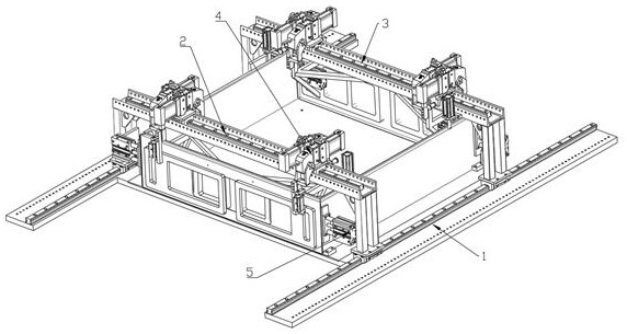
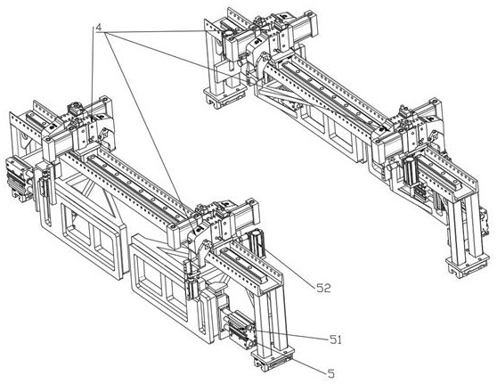
[0025] like Figure 1 to Figure 3 As shown, Embodiment 1 of the present invention: a clamping device for LED display box welding, including a tooling platform 1, a first gantry 2, a second gantry 3, a clamping mechanism 4 and a pusher Mechanism 5, the first gantry 2 and the second gantry 3 are arranged in parallel on the tooling platform 1, and the bottoms of the first gantry 2 and the second gantry 3 are both slidably connected to the tooling platform On the platform 1, the clamping mechanisms 4 are evenly distributed on the first gantry 2 and the second gantry 3, and the pushing mechanism 5 is respectively arranged on the first gantry 2 and the second gantry. On the inner side of the column and the beam of the second gantry frame 3, the first gantry frame 2 and the second gantry frame 3 are used to install the clamping mechanism 4, and the tooling platform 1 is used to place the boxes to be welded The clamping mechanism 4 is used to firmly and stably clamp the box to be wel...


PUM


Abstract

The invention discloses a clamping device for LED display screen box body welding. The clamping device comprises a tool flat plate table, a first portal frame, a second portal frame, clamping mechanisms and pushing mechanisms; the first portal frame and the second portal frame are arranged on the tool flat plate table in parallel; the bottom of the first portal frame and the bottom of the second portal frame are both glidingly connected to the tool flat plate table; the clamping mechanisms are evenly distributed on the first portal frame and the second portal frame; the pushing mechanisms are arranged on the inner sides of stand columns and cross beams of the first portal frame and the second portal frame correspondingly; the clamping mechanisms are used for firmly and stably clamping to-be-welded box bodies; and the pushing mechanisms are used for tightly pushing the to-be-welded box bodies to prevent the to-be-welded box bodies from moving. According to the clamping device, welding position deviation caused by clamping can be effectively avoided, clamping is stable, the welding efficiency is high, the welding quality is firm, the welding reject ratio is greatly reduced, the production benefit is effectively improved, and the good market application value is achieved.

Description

technical field [0001] The invention relates to the technical field of welding and clamping equipment, in particular to a clamping device used for welding of LED display screen boxes. Background technique [0002] With the continuous development of technology and the continuous improvement of machining level, automatic welding technology has become more and more widely used. The use of automatic welding technology to replace traditional manual welding operations can reduce the damage to the human body caused by welding operations and improve welding efficiency. Since the welding quality directly affects the performance of the product, the factors affecting the welding quality in the welding process cannot be ignored. Among them, whether the workpiece is clamped and fixed in the automatic welding technology has a great impact on the welding quality. When welding, it is often measured manually and clamped by clamps through bolts, and then the butt joints between the plates are...

Claims


Application Information

Patent Timeline
Patent Type & Authority Applications(China)
IPC IPC(8): B23K37/04
CPCB23K37/0435
Inventor 刘迪红
Owner SHENZHEN BAKO OPTOELECTRONICS CO LTD
Why Eureka
Try Eureka