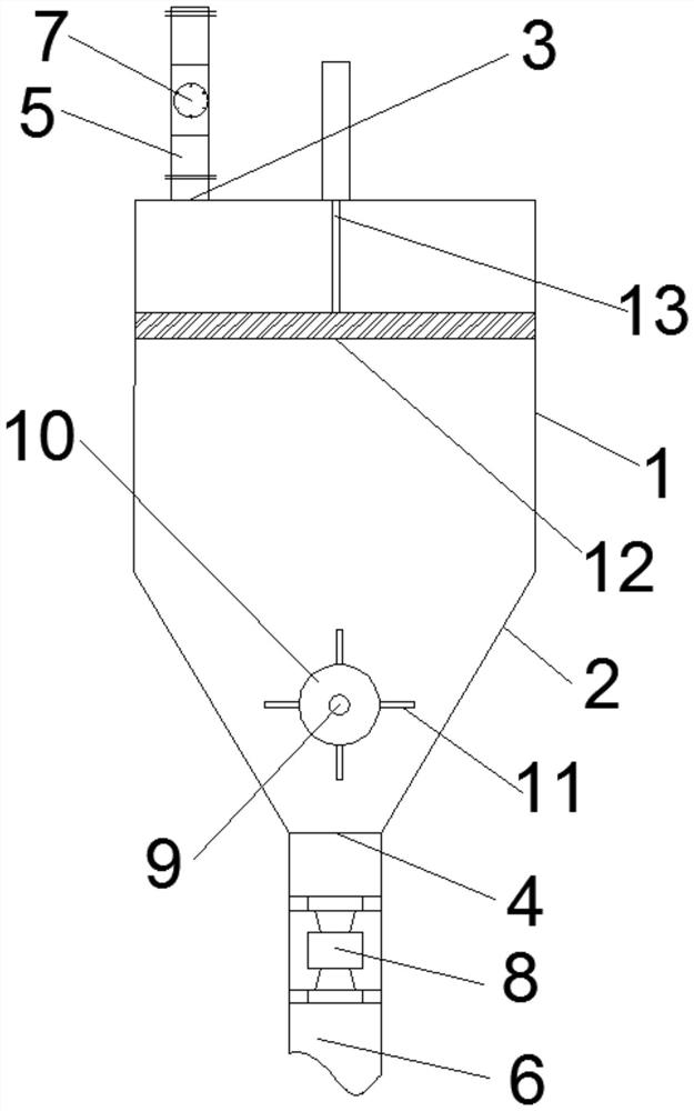
Nitrate slurry thickener
A thickener and nip slurry technology, applied in the field of nip slurry thickener, can solve the problems of easy blockage of the discharge port and low degree of automation
- Summary
- Abstract
- Description
- Claims
- Application Information
AI Technical Summary
Problems solved by technology
Method used
Image
Examples
Embodiment 1
[0029] A nitrate slurry thickener, comprising a cylinder, the cylinder includes a cylinder part at the top and a cone part at the bottom, the top wall of the cylinder part is provided with a feed inlet, and the bottom of the cone part is The wall is provided with a discharge port, the feed port is connected with a feed pipe, the discharge port is connected with a discharge pipe, an electric control valve is installed on the feed pipe, and an electronic meter is installed in the discharge pipe. The heavy flow device, the anti-blocking device is installed in the cone part above the discharge port.
[0030] Through this setting, the nitric acid slurry enters the cylinder from the feed pipe for sedimentation and thickening, and the thickened nitric slurry is discharged from the discharge pipe. An electric control valve is installed on the feed pipe to accurately control the feeding speed of the nip slurry. An electronic weighing flow device is installed in the discharge pipe to fa...
Embodiment 2
[0032] On the basis of Embodiment 1, the anti-blocking device includes a rotating shaft arranged radially along the cylinder, a rotating roller is set on the rotating shaft, and several fins are installed on the rotating roller along the circumference of the rotating roller. A driving motor for driving the rotating shaft to rotate is installed outside the body. Through this setting, the drive motor drives the rotating shaft to rotate, and the rotating roller installed on the rotating shaft rotates accordingly, so that the fins can stir the nitrogen slurry above the outlet, preventing the nitrogen slurry from being blocked at the outlet and affecting the nitrogen slurry. Normal discharge.
Embodiment 3
[0034]On the basis of the above-mentioned embodiments, an annular scraper is installed along the inner wall of the cylindrical part, a connecting frame is installed on the inner side of the annular scraper, and an electric telescopic is installed outside the top wall of the cylindrical part. The output end of the electric telescopic rod passes through the top wall of the cylinder part and is connected with the connecting frame. Through this setting, the nitrate slurry attached to the inner wall of the column can be cleaned, preventing the nitrate slurry from accumulating on the inner wall, affecting the settling speed of the nitrate slurry, and improving the thickening efficiency of the nitrate slurry.
PUM
 Abstract
Description
Claims
Application Information
 - R&D Engineer
- R&D Manager
- IP Professional
- Industry Leading Data Capabilities
- Powerful AI technology
- Patent DNA Extraction
Browse by: Latest US Patents, China's latest patents, Technical Efficacy Thesaurus, Application Domain, Technology Topic, Popular Technical Reports.
© 2024 PatSnap. All rights reserved.Legal|Privacy policy|Modern Slavery Act Transparency Statement|Sitemap|About US| Contact US: help@patsnap.com


