
Self-adaptive lattice type 3D printing helmet buffer layer and manufacturing method thereof

A 3D printing, self-adaptive technology, applied in helmets, helmet caps, applications, etc.

Pending Publication Date: 2021-04-30
NANJING AMEBA ENG STRUCTURE OPTIMIZATION RES INST CO LTD
View PDF6 Cites 1 Cited by
  • Summary
  • Abstract
  • Description
  • Claims
  • Application Information

AI Technical Summary

Problems solved by technology

[0006] The purpose of the present invention is to provide an adaptive lattice type 3D printing helmet cushioning layer and its manufacturing method, to solve the problems existing in the prior art, to produce a good buffering effect on the tangential impact force of the helmet, thereby reducing the tangential impact force. The risk of damage to the human neck and spine caused by the impact force

Method used


Image

  • Self-adaptive lattice type 3D printing helmet buffer layer and manufacturing method thereof
  • Self-adaptive lattice type 3D printing helmet buffer layer and manufacturing method thereof
  • Self-adaptive lattice type 3D printing helmet buffer layer and manufacturing method thereof

Examples


Embodiment 1

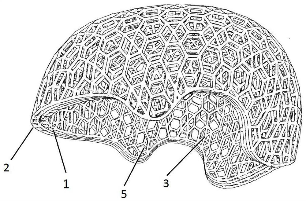
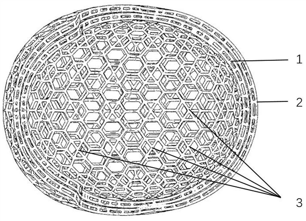
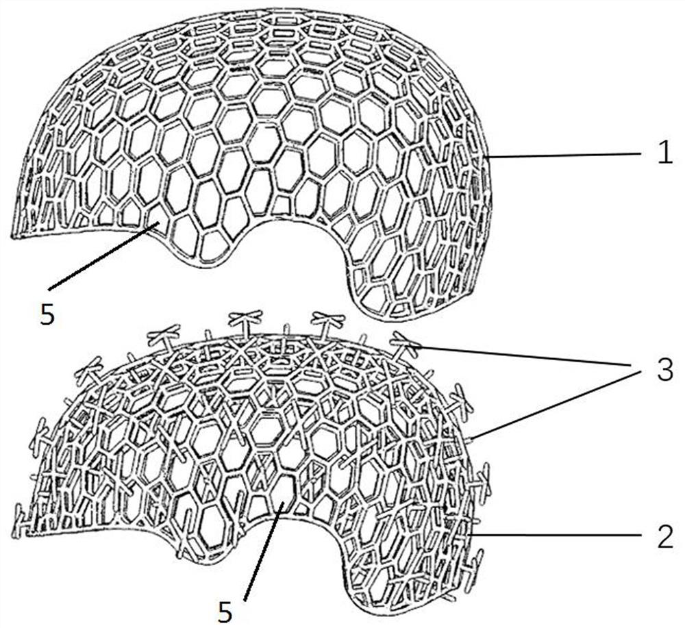
[0037] Such as Figure 1~Figure 3 As shown, this embodiment provides an adaptive lattice-type 3D printed helmet buffer layer, including an inner truss 1 and an outer truss 2, the outer truss 2 is arranged outside the inner truss 1, and is connected by a support unit , the stiffness of the support unit is less than that of the outer truss 2 and its inner truss 1, and there is a gap between the inner truss 1 and the outer truss 2 that allows them to slide tangentially relative to each other.

[0038] In this embodiment, there is a gap between the outer truss 2 and the inner truss 1, which provides conditions for the relative tangential slip of the two, and the stiffness of the support unit is smaller than the stiffness of the outer truss 2 and the inner truss 1, so that the support Elements are more prone to deformation. When the buffer layer is impacted by the outside world, the impact force can be divided into the normal force perpendicular to the contact surface and the tang...

Embodiment 2

[0047] This embodiment also provides a method for making an adaptive lattice type 3D printing helmet cushioning layer, comprising the following steps:

[0048] 1) Use design software to establish a digital model of the buffer layer;

[0049] 2) Import the digital model into a 3D printer for printing.

[0050] In step 1), digital models of the forehead surface 7, the top surface of the head 8, the left side 9, the right side 10, and the back side of the brain 115 were respectively established; in step 2), the forehead surface 7, the top surface of the head 8, and the left side were printed respectively. Side 9, the right side 10, and the back side of the head 115, after the printing is completed, the adjacent parts are bonded.

[0051] The design process is as follows:

[0052] (1) Design the inner truss 1: Firstly, the inner head shape surface is established according to the size of the user’s head shape obtained by surveying and mapping. The inner hexagonal mesh surface, a...


PUM


Abstract

The invention relates to the technical field of buffer damping structures, in particular to a self-adaptive lattice type 3D printing helmet buffer layer and a manufacturing method thereof. The buffer layer comprises an inner layer truss and an outer layer truss, the outer layer truss is arranged on the outer side of the inner layer truss and connected to the inner layer truss through a supporting unit, the rigidity of the supporting unit is smaller than that of the outer layer truss and the inner layer truss, and a gap allowing the inner layer truss and the outer layer truss to relatively generate tangential sliding is formed between the inner layer truss and the outer layer truss; when the buffer layer is impacted by the outside, the outer layer truss and the inner layer truss slide relatively and can play a role in buffering tangential force, so that the risk that the tangential force causes damage to the neck and the spine of a human body is reduced; and the rod pieces of the truss structures are subjected to tensile deformation, and can also perform buffering effect on the normal impact force.

Description

technical field [0001] The invention relates to the technical field of cushioning and shock-absorbing structures, in particular to an adaptive lattice type 3D printing helmet cushioning layer and a manufacturing method thereof. Background technique [0002] The function of the helmet is to reduce the damage to the head due to inertia and collision in the event of an accident. A traditional helmet consists of a shell, a buffer layer, a comfortable pad, and a wearing device. The buffer layer, as the most important energy dissipation component inside the helmet, is the design focus of the helmet's impact resistance. [0003] When the head is subjected to external impact, the impact force can be decomposed into vertical impact force and shear impact force. The vertical impact force causes the translational acceleration of the head, which may cause skull fracture and other injuries. Rotational acceleration, which may cause spinal torsion and other injuries. [0004] The traditi...

Claims


Application Information

Patent Timeline
IPC IPC(8): A42B3/06B29C64/386B33Y50/00B33Y80/00
CPCA42B3/064B29C64/386B33Y50/00B33Y80/00
Inventor 沈炜丁颖屈会建
Owner NANJING AMEBA ENG STRUCTURE OPTIMIZATION RES INST CO LTD
Learn More