


Quick Research
Generate reliable direction feasibility study reports for your R&D in just a few steps.

Technical Q&A
Discover and master advanced knowledge NOW. Basics, ideas, possibilities, all at once.

Find Solutions
As an expert in R&D theories, this can generate solutions to your technical problems instantly.

Evaluate Feasibility
Analyze your overall solution with one click, know your potential R&D risks in advance.

Monitor Landscape
Get weekly tech updates, stay abreast of the latest tech innovations and key insights.
Brake device for tubular motor and tubular motor
A brake device, tubular motor technology, applied in electromechanical devices, electrical components, electric components, etc., can solve problems such as poor braking effect
- Summary
- Abstract
- Description
- Claims
- Application Information
AI Technical Summary
Problems solved by technology
Method used
Image

Examples
Embodiment 1
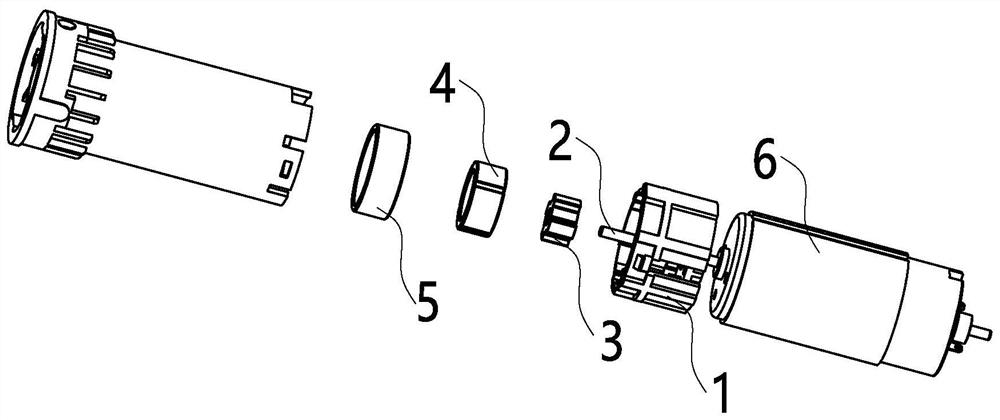
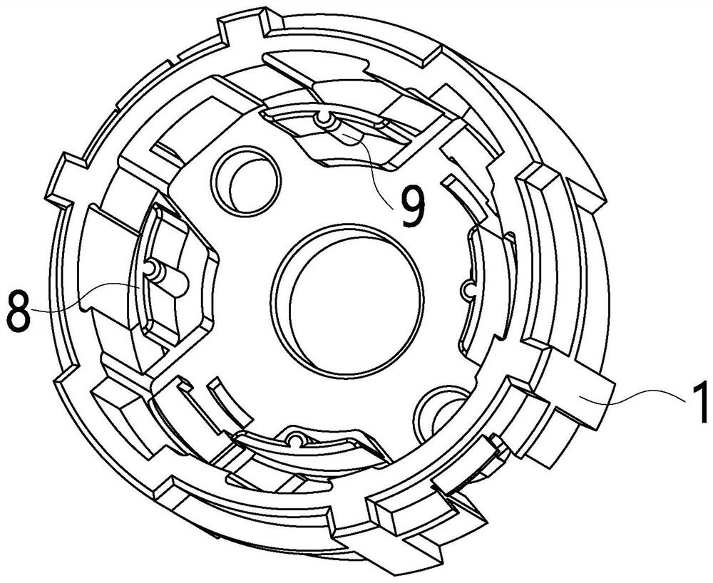
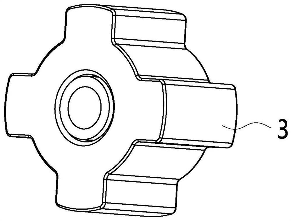
[0031] Such as Figure 1 to Figure 6 As shown, the preferred structure of the brake device for tubular motors in this embodiment includes a housing 1, a magnetically permeable rotor 3 for fixed connection with the motor shaft 2, a magnet 4 and an outer part for being located in the magnetic circuit of the magnet 4 The magnetizer 5, the magnetizer rotor 3 is a magnetizer 4, the magnet 4 is located outside the magnetizer rotor 3, and the magnet is along the radial direction of the magnetizer rotor 3 and between the magnetizer rotor 3 There is a gap between them, the external magnetizer 5 and the magnetizer rotor 3 are magnetically connected to the magnet 4 , and the magnet 4 is fixed relative to the housing 1 .
[0032] After adopting the above-mentioned structure, firstly, the brake device includes a casing 1, a magnetically conductive rotor 3 for fixed connection with the motor shaft 2, a magnet 4, and an external magnetically conductive body 5 for being located in the magneti...
Embodiment 2
[0044] The difference between this embodiment and Embodiment 1 is that in this embodiment, the external magnetizer 5 is in direct contact with the magnetic ring, and the closer the distance between the outer magnetizer 5 and the magnet 4, the greater the intensity of the magnetic field. With this structure, the contact between the external magnetic conductor 5 and the magnet 4 can maximize the strength of the magnetic field of the magnet 4, so that the torsional moment during braking is larger. This embodiment can also achieve the technical effect of the first embodiment.
Embodiment 3
[0046] The difference between this embodiment and Embodiment 1 is that in this embodiment, the magnet 4 is a bar magnet and includes at least two bar magnets, and the at least two bar magnets are evenly distributed along the circumferential direction of the motor shaft. distribution, this embodiment can also achieve the technical effect of the first embodiment.
PUM
 Abstract
Description
Claims
Application Information
 - R&D Engineer
- R&D Manager
- IP Professional
- Industry Leading Data Capabilities
- Powerful AI technology
- Patent DNA Extraction
Browse by: Latest US Patents, China's latest patents, Technical Efficacy Thesaurus, Application Domain, Technology Topic, Popular Technical Reports.
© 2024 PatSnap. All rights reserved.Legal|Privacy policy|Modern Slavery Act Transparency Statement|Sitemap|About US| Contact US: help@patsnap.com