Downtime fault positioning method and device

A fault location and downtime technology, applied in the software field, can solve problems such as inaccuracy and low efficiency of downtime fault location.

Pending Publication Date: 2021-04-27
INSPUR SUZHOU INTELLIGENT TECH CO LTD
View PDF2 Cites 0 Cited by
  • Summary
  • Abstract
  • Description
  • Claims
  • Application Information

AI Technical Summary

Problems solved by technology

[0005] The embodiment of the present invention solves the technical problem of low efficiency and inaccurate positioning of downtime faults during startup by providing a method and device for locating downtime faults

Method used


Image

  • Downtime fault positioning method and device
  • Downtime fault positioning method and device
  • Downtime fault positioning method and device

Examples


Embodiment approach

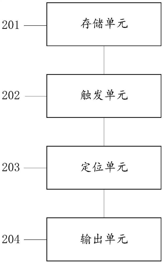
[0057] In an optional implementation manner, the downtime fault location unit 203 includes:

[0058] A judging subunit, used to judge whether the boot process data includes an Exception function;

[0059] The processing subunit is used to locate the downtime fault based on the Exception function if the data of the startup process includes the Exception function, and obtain the downtime fault information.

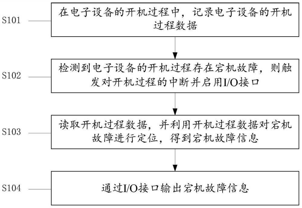
[0060] In an optional embodiment, the booting process data includes: the booting guide module used in the booting process of the electronic device, recorded related events, called function entry and function exit, recorded actual booting time, and booting process nodes passed ; Wherein, the power-on guidance module is used to guide the power-on process of the electronic device, and the power-on process node is used to divide two adjacent power-on stages in the power-on process.

[0061] In an optional implementation manner, the trigger unit 202 is specifically used for:

...


PUM


Abstract

The invention discloses a downtime fault positioning method and device, and the method comprises the steps: recording the starting process data of electronic equipment in the starting process of the electronic equipment; when it is detected that a downtime fault exists in the starting process of the electronic equipment, triggering interruption of the starting process, and starting an I / O interface; reading startup process data, and positioning a downtime fault by utilizing the startup process data to obtain downtime fault information; and outputting downtime fault information through an I / O interface. The technical problem that downtime fault positioning in the startup process is low in efficiency and not accurate enough is solved.

Description

technical field [0001] The invention relates to the field of software technology, in particular to a downtime fault location method and device. Background technique [0002] In the research and development stage of computers, especially servers, there will be many downtime problems during restart tests or other tests, and because of the complexity of the server itself, the startup speed is much slower than that of a personal computer. In order to test efficiency or simulate real Generally, the debug mode will not be enabled in the usage scenario, so if there is a crash during the boot process, there will be no serial port available and no diagnostic data or crash logs. Locate the downtime problem. [0003] The traditional positioning method is: according to the POST code (Post Code) during the boot process, BMC (Baseboard Management Controller, baseboard management controller) log records and downtime fault diagnosis function, collect the information in the computer registe...

Claims


Application Information

Patent Timeline
Patent Type & Authority Applications(China)
IPC IPC(8): G06F11/07
CPCG06F11/079G06F11/0706
Inventor 杨少俊王兵姚藩益钱慧娟
Owner INSPUR SUZHOU INTELLIGENT TECH CO LTD
Why Eureka
Try Eureka