
A kind of automatic assembly equipment for switching power supply pressure strip

A technology of automatic assembly and switching power supply, which is applied in the direction of metal processing equipment, metal processing, manufacturing tools, etc., can solve the problems of slow efficiency and achieve the effect of improving assembly efficiency and high degree of automation

Active Publication Date: 2022-07-15
CHANGZHOU CHUANGLIAN POWER SUPPLY TECH CO LTD
View PDF0 Cites 0 Cited by
  • Summary
  • Abstract
  • Description
  • Claims
  • Application Information

AI Technical Summary

Problems solved by technology

[0003] The technical problem to be solved by the present invention is: in order to solve the problem that the efficiency of manually assembling the heat-shrinkable insulating sleeve on the bead is relatively slow and cannot meet the existing production requirements, the present invention provides an automatic assembly of the bead of a switching power supply The equipment uses a stepping motor to drive the turntable to perform step-by-step rotation. During the rotation process, the heat-shrinkable insulating sleeve can be automatically assembled to the bead through the bead feeding device, the heat-shrinkable insulating sleeve feeding device, and the sleeve propulsion device. On the other hand, the perforation and blanking device can not only perforate the heat-shrinkable insulating sleeve on the briquette, but also feed the perforated briquette to the heat-shrinking mechanism, and the heat-shrinking mechanism can heat the briquette to make it The heat-shrinkable insulating sleeve can wrap the bead, and the invention has a high degree of automation, which greatly improves the assembly efficiency of the bead

Method used


Image

  • A kind of automatic assembly equipment for switching power supply pressure strip
  • A kind of automatic assembly equipment for switching power supply pressure strip
  • A kind of automatic assembly equipment for switching power supply pressure strip

Examples


Embodiment Construction

[0040] The technical solutions of the present invention will be clearly and completely described below with reference to the accompanying drawings. Obviously, the described embodiments are a part of the embodiments of the present invention, but not all of the embodiments.

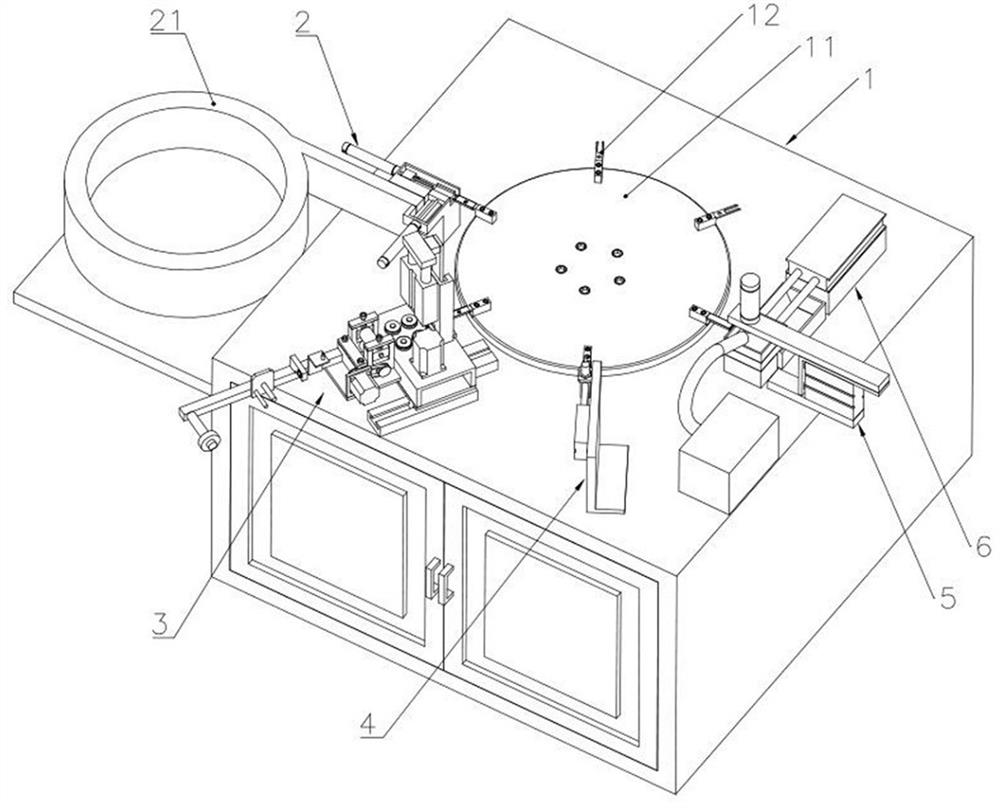
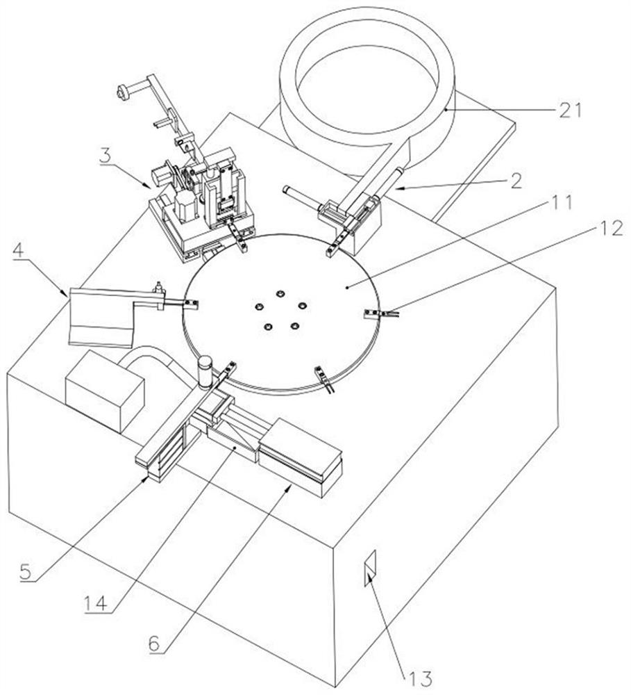
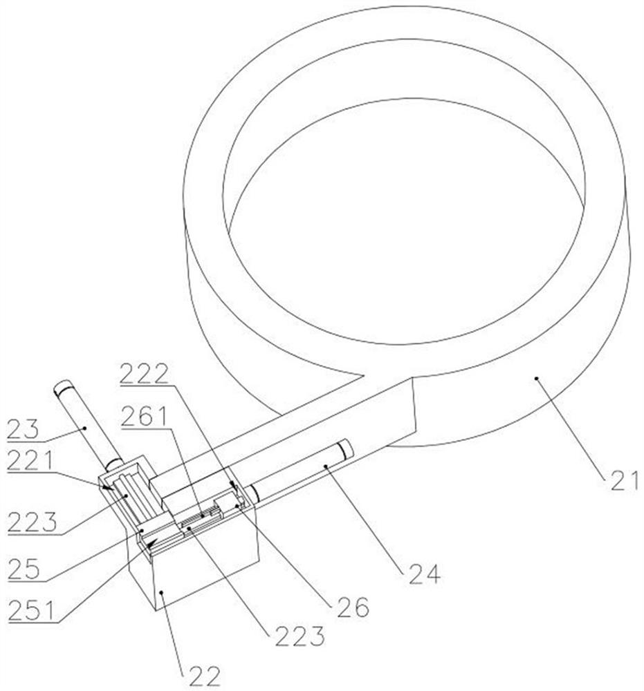
[0041] like Figure 1-9 As shown in the figure, an automatic assembling equipment for switching power supply layering includes: a processing table 1, on which is provided a turntable 11 and a stepping motor for driving the turntable 11 to perform step-by-step rotation, the turntable 11 is provided with several The carrier jig 12, the carrier jig 12 includes a connecting block 121 connected to the turntable 11 and a carrier bar 122 for carrying the bead; a bead loading device 2 for placing the bead on the carrier bar 122; heat shrinkable insulation The sleeve feeding device 3 is used to sleeve the heat-shrinkable insulating sleeve on one end of the bead, and the heat-shrinkable insulating sleeve feeding devi...


PUM


Abstract

The invention belongs to the field of switching power supplies, and relates to an automatic assembling equipment for switching power supply layers, comprising: a processing table, a turntable and a stepping motor are arranged on the processing table, a plurality of bearing jigs are arranged on the turntable, and the bearing jigs comprise connecting blocks And the carrying strip, the pressure strip feeding device, the heat shrinkable insulating sleeve feeding device, the heat shrinkable insulating sleeve feeding device includes the bottom plate and the casing conveying mechanism, the casing spreading mechanism and the casing cutting mechanism arranged on the bottom plate in sequence. , There is a track under the bottom plate and a first cylinder for driving the bottom plate to move in the direction of the track, a casing pushing device, a punching and cutting device, a heat shrinking mechanism, a layer feeding device, a heat shrinkable insulating sleeve feeding device, and a casing The propulsion device and the punching and unloading device are arranged in sequence along the rotation direction of the turntable, and the heat shrinking mechanism is arranged on the lower side of the perforating cone, and accepts the pressing blocks removed by the perforating and unloading device. The invention realizes automatic assembly of the bead, and improves the assembly efficiency of the bead.

Description

technical field [0001] The invention relates to the field of switching power supplies, in particular to an automatic assembling device for pressing strips of switching power supplies. Background technique [0002] Switching power supply, also known as switching power supply and switching converter, is a high-frequency electric energy conversion device and a type of power supply. like Figure 10 and Figure 11 As shown, the pressure bar is one of the important components in the switching power supply. The function of the pressure bar is to press the other components by screwing with the threaded holes on the pressure bar. However, since the bead itself is not made of insulating material, it is necessary to insulate the heat-shrinkable insulating sleeve on the bead, otherwise the bead may cause failure of the switching power supply due to conduction. Traditionally, the heat shrinkable insulating sleeve is assembled on the bead by manual assembly, such as Figure 12 As shown...

Claims


Application Information

Patent Timeline
Patent Type & Authority Patents(China)
IPC IPC(8): B23P19/027B23P19/00
CPCB23P19/027B23P19/00
Inventor 邢立龙唐景新
Owner CHANGZHOU CHUANGLIAN POWER SUPPLY TECH CO LTD
Learn More