Convenient hand sanitizer mounting device
A technology for installing devices and hand sanitizers, which can be applied to household appliances, brackets or dispensers, sanitary equipment, etc., can solve the problem of troublesome removal of paper towels, and achieve the effects of simple operation, convenient removal, and prevention of dumping.
- Summary
- Abstract
- Description
- Claims
- Application Information
AI Technical Summary
Problems solved by technology
Method used
Image
Examples
Embodiment 1
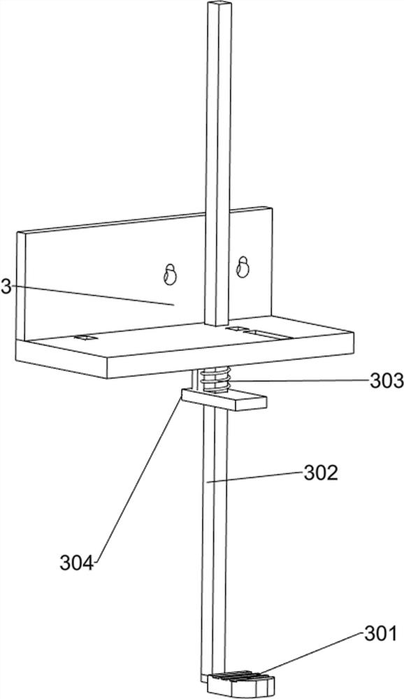
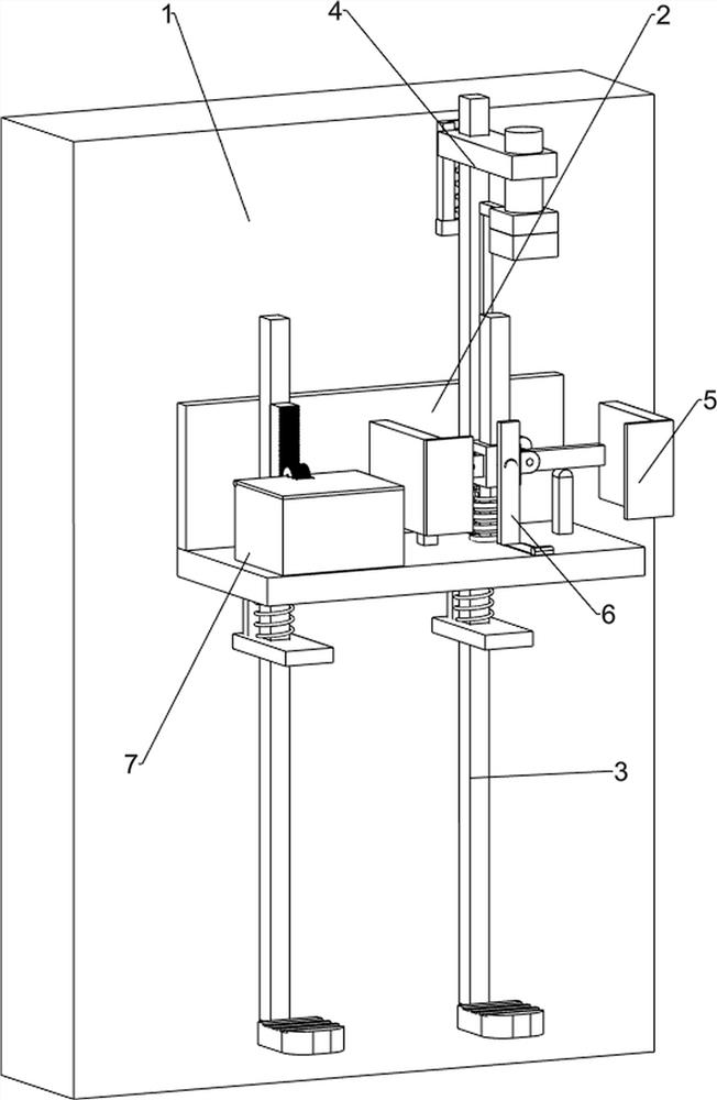
[0027] A handy hand sanitizer mount like figure 1 , figure 2 with image 3 As shown, it includes a wall 1, a support seat 2, a stepping mechanism 3 and a pressing mechanism 4. The front middle part of the wall 1 is connected with a support seat 2, and the right side of the support seat 2 is provided with a stepping mechanism 3. The upper part of the wall body 1 is connected with the stepping mechanism. A pressing mechanism 4 is arranged between the mechanisms 3 .
[0028] When the user needs to use hand sanitizer, first place the hand sanitizer on the upper right front side of the support base 2, then step down on the stepping mechanism 3 to drive the pressing mechanism 4 to move, so that the hand sanitizer can be squeezed out, and the hand sanitizer can be used Wash your hands so that you can easily squeeze out the hand sanitizer without bending over.
[0029] The stepping mechanism 3 includes a first pedal 301, a first pedal column 302, a first spring 303 and a first con...
Embodiment 2
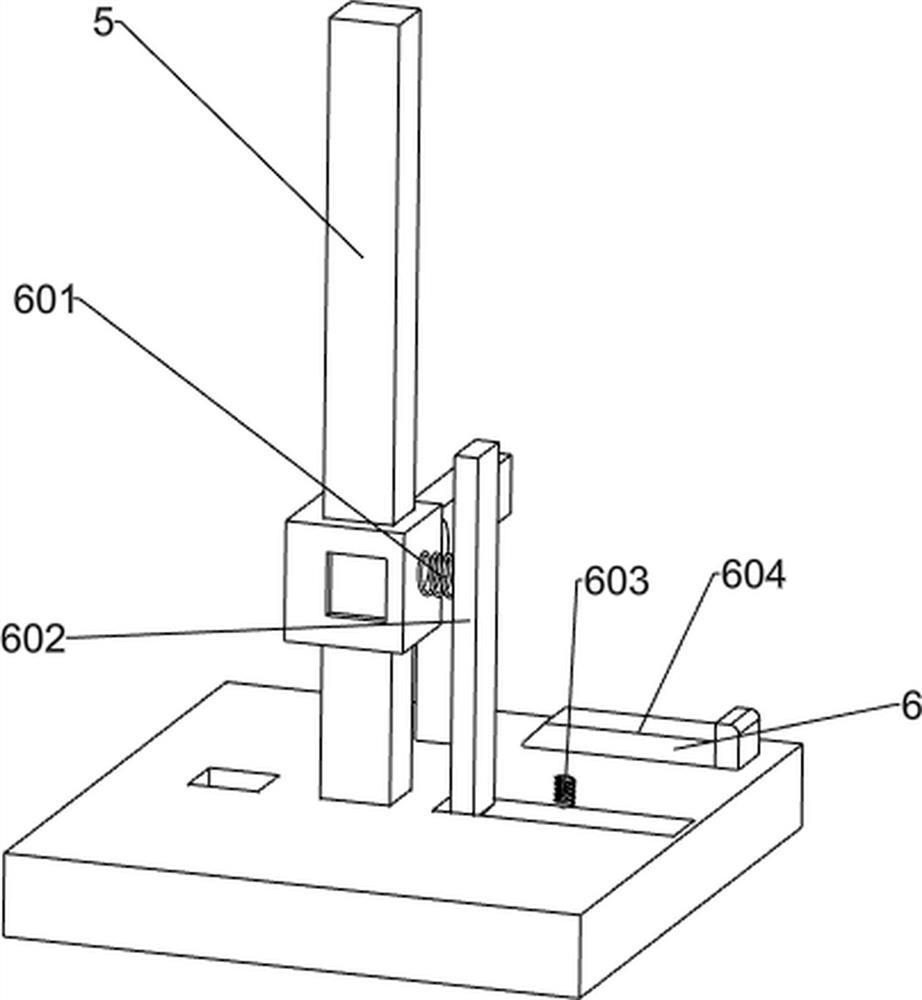
[0033] On the basis of Example 1, such as Figure 4 , Figure 5 with Image 6 As shown, a clamping assembly 5 is also included. The clamping assembly 5 includes a main shaft 502, a moving block 503, a lifting shaft 504, a splint 505, a pillar 506 and a third spring 507, and a contact rod 501 is connected above the pressing block 405. The contact rod 501 is connected with the pressing bar 404, the main shaft 502 is connected to the upper right rear side of the support seat 2, the moving block 503 is slidably connected to the upper side of the main shaft 502, and the third spring is connected between the lower side of the moving block 503 and the support seat 2 507, the third spring 507 is sleeved on the main shaft 502, the moving block 503 cooperates with the contact rod 501, the left and right sides of the moving block 503 are connected with the lift shaft 504 in rotation, and the outside of the lift shaft 504 is connected with a splint 505, supporting The right side of the ...
PUM
 Abstract
Description
Claims
Application Information
 - Generate Ideas
- Intellectual Property
- Life Sciences
- Materials
- Tech Scout
- Unparalleled Data Quality
- Higher Quality Content
- 60% Fewer Hallucinations
Browse by: Latest US Patents, China's latest patents, Technical Efficacy Thesaurus, Application Domain, Technology Topic, Popular Technical Reports.
© 2025 PatSnap. All rights reserved.Legal|Privacy policy|Modern Slavery Act Transparency Statement|Sitemap|About US| Contact US: help@patsnap.com


