Supercharge Your Innovation With Domain-Expert AI Agents!

Dehumidifier for power distribution

A technology for dehumidifiers and power distribution boxes, which is applied in substation/power distribution device shells, instruments, electrical components, etc., which can solve problems such as inability to effectively remove moisture in power distribution cabinets, so as to prolong service life and reduce damp and rust Effect

Pending Publication Date: 2021-04-23
HUZHOU ELECTRIC POWER SUPPLY CO OF STATE GRID ZHEJIANG ELECTRIC POWER CO LTD
View PDF6 Cites 2 Cited by
  • Summary
  • Abstract
  • Description
  • Claims
  • Application Information

AI Technical Summary

Problems solved by technology

[0004] The purpose of the present invention is to provide a dehumidifier for power distribution to solve the problem that the moisture inside the power distribution cabinet cannot be effectively removed in the above-mentioned background technology

Method used


Image

  • Dehumidifier for power distribution
  • Dehumidifier for power distribution
  • Dehumidifier for power distribution

Examples


Embodiment 1

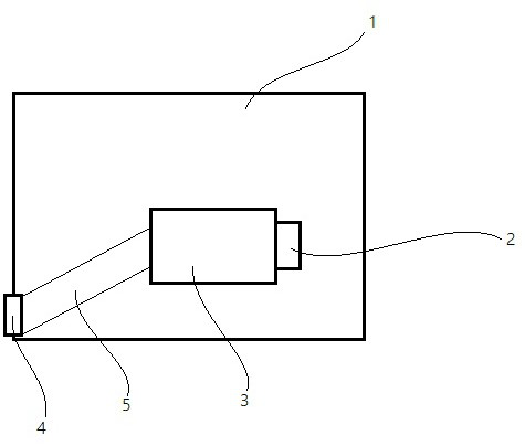
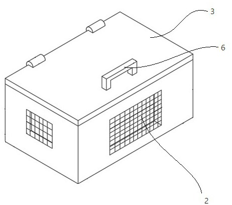
[0030] like figure 1 As shown, a dehumidifier for power distribution is used for dehumidification of a distribution box, including a box body 1, an air inlet pipe 5, a blower mechanism, two humidity sensors, a temperature sensor, a heating wire and a controller. The box body 1 has an air inlet 4 and an air outlet 2, such as figure 2 As shown, a box door is provided on the top of the box body 1, and the box door is connected to the box body 1 through a hinge rotation, and a handle 6 is provided on the box door, which is convenient for inspection and maintenance of internal components, timely discovering component failures, and extending lifespan of the dehumidifier.

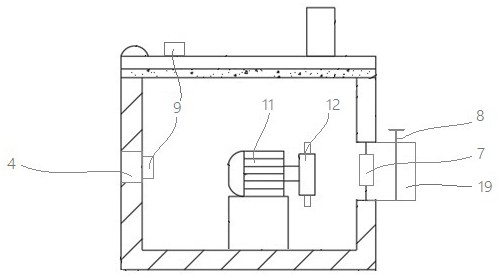
[0031] like image 3 As shown, the air inlet 4 communicates with the outside of the distribution box through the air inlet pipe 5, and the air inlet 4 is inclined upward along the direction of the airflow.

[0032] In this embodiment, a filter screen is installed inside the air inlet 4 . The 4 places of the a...

Embodiment 2

[0039]The structure of the box body of this embodiment is the same as that of the dehumidifier, and only the electromagnetic valve in Embodiment 1 is replaced with a wind section, a guide plate and a steering gear. Wherein, the air outlet 23 is provided with a guide plate, and the guide plate is installed obliquely downward. In the main pipe 21, an air section is arranged near one end of the box body 1, on which a steering gear is arranged, the air section is connected to the main pipe 21 in rotation, and the steering gear is connected to the controller. The air section and the guide plate play the role of directional delivery of hot air.

[0040] When the humidity sensor detects that the humidity in the distribution box is higher than the set threshold, the controller makes the steering gear work, opens the air section, and delivers hot air to the distribution box. If only a certain corner of the distribution box has some water accumulation, the dehumidifier can also dehumid...


PUM


Abstract

The invention relates to the technical field of electrical equipment, in particular to a dehumidifier for power distribution, which is used for dehumidifying a power distribution box. The dehumidifier comprises a box body, an air inlet pipe, an air blowing mechanism, two humidity sensors, a temperature sensor, an electric heating wire and a controller; the box body is provided with an air inlet and an air outlet, and the electric heating wire is installed on the inner side of the air outlet. the temperature sensor is installed between the electric heating wire and the air outlet, the air blowing mechanism comprises a shell, a driving motor and a fan, the shell is fixedly connected with the box body, the two humidity sensors detect the air humidity at the air inlet and in the distribution box respectively, and the electric heating wire, the driving motor, the humidity sensors and the temperature sensor are all connected with the controller. The dehumidifier has the beneficial effects that through the design of the air blowing structure, the air blowing mechanism generates air, the air is heated by the electric heating wire to become hot air and is exhausted to dehumidify the power distribution cabinet, the possibility that metal facilities are affected with damp and rusted, switch equipment is short-circuited or facilities in the power distribution cabinet are damaged is reduced, and the service life of the power distribution cabinet is prolonged.

Description

technical field [0001] The invention relates to the technical field of electrical equipment, in particular to a dehumidifier for power distribution. Background technique [0002] Dehumidifiers have another name called dehumidifiers, dehumidifiers, and dehumidifiers belong to a small member of the refrigeration and air conditioning family. In power distribution places such as power distribution cabinets, the metal facilities in them are often damp and rusted due to too much humidity in the space, resulting in short circuits, sudden tripping of switchgear, and even damage to the facilities in the power distribution cabinet. Therefore, dehumidifiers need to be configured in power distribution places such as power distribution cabinets. The common dehumidifiers generally rely on fans to blow the air to dehumidify, but simply using fans to dehumidify cannot completely remove the moisture inside the power distribution cabinet, and may still cause damage to the power distribution ...

Claims


Application Information

Patent Timeline
Patent Type & Authority Applications(China)
IPC IPC(8): H02B1/48H02B1/56H02B1/28G05D27/02
CPCH02B1/48H02B1/565H02B1/28G05D27/02
Inventor 张龙超张千斌徐国华赵志修蔡震曾鑫朱翔钟钦
Owner HUZHOU ELECTRIC POWER SUPPLY CO OF STATE GRID ZHEJIANG ELECTRIC POWER CO LTD
Features
  • R&D
  • Intellectual Property
  • Life Sciences
  • Materials
  • Tech Scout
  • Unparalleled Data Quality
  • Higher Quality Content
  • 60% Fewer Hallucinations
Learn More