
Tracking and scanning system, calibration method and measurement method of relay tracker

A technology of tracking system and calibration method, applied in the field of tracking and scanning system of relay tracker

Active Publication Date: 2021-04-23
ZG TECH CO LTD
View PDF0 Cites 0 Cited by
  • Summary
  • Abstract
  • Description
  • Claims
  • Application Information

AI Technical Summary

Problems solved by technology

[0004] In view of this, it is necessary to provide a tracking scanning system, a calibration method and a measuring method of a relay tracker to solve the problem of how to perform tracking scanning with complete coverage and high precision

Method used


Image

  • Tracking and scanning system, calibration method and measurement method of relay tracker
  • Tracking and scanning system, calibration method and measurement method of relay tracker
  • Tracking and scanning system, calibration method and measurement method of relay tracker

Examples


Embodiment 1

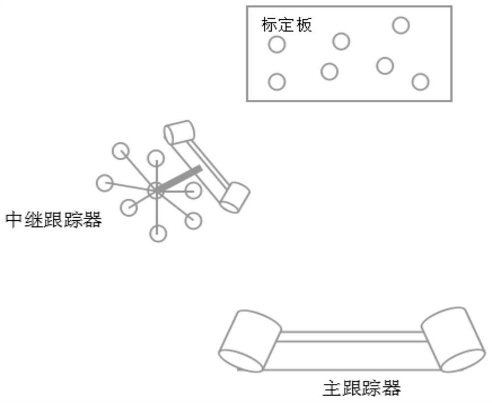
[0046] An embodiment of the present invention provides a tracking and scanning system for a relay tracker, combining figure 1 look, figure 1 The structure diagram of the tracking and scanning system of the relay tracker provided by the present invention, the system includes a calibration plate containing a known calibration coordinate system, a main tracker with tracking function and a plurality of relay trackers with tracking targets and tracking Function, wherein multiple relay trackers form a cascade structure, and each relay tracker is used to be tracked by the upper level relay tracker and / or used to track the lower level relay tracker.

[0047] In the tracking and scanning system of the relay tracker provided by the embodiment of the present invention, a new relay tracker is defined in the tracking and scanning system of the relay tracker, which not only has the tracking function, but also can be used by other The relay tracker tracks to form a cascaded relay structure....

Embodiment 2

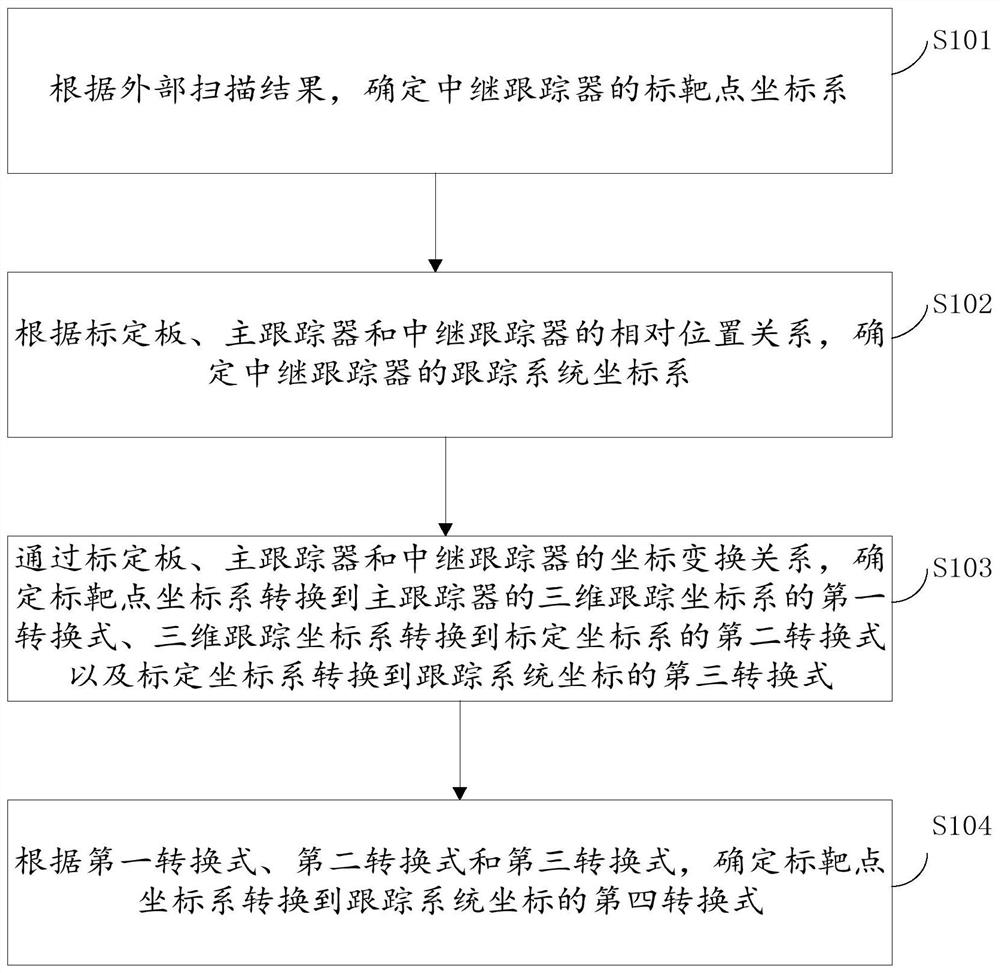
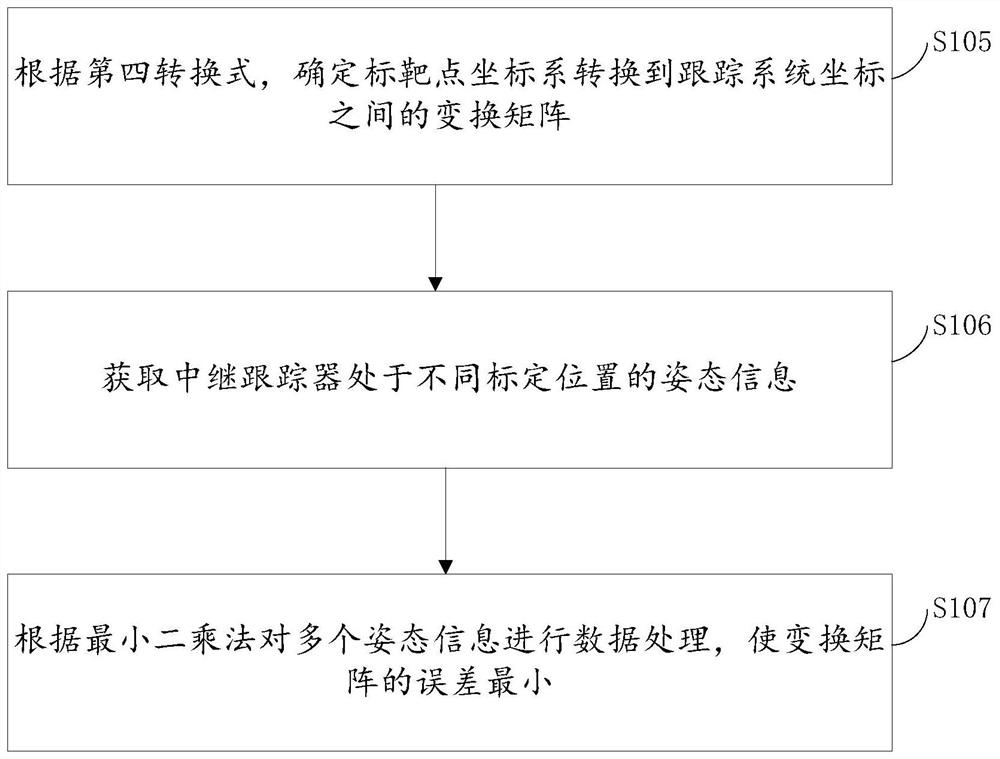
[0049] An embodiment of the present invention provides a calibration method for a relay tracker, combining figure 2 look, figure 2 It is a schematic flow chart of the calibration method of the relay tracker provided by the present invention. The above calibration method is based on the tracking and scanning system of the relay tracker in Embodiment 1. The above calibration method of the relay tracker includes steps S101 to S104, wherein:

[0050] In step S101, determine the target point coordinate system of the relay tracker according to the external scanning result;

[0051] In step S102, determine the tracking system coordinate system of the relay tracker according to the relative positional relationship of the calibration board, the main tracker and the relay tracker;

[0052] In step S103, through the coordinate transformation relationship of the calibration board, the main tracker, and the relay tracker, determine the first conversion formula for converting the target ...

Embodiment 3

[0089] An embodiment of the present invention provides a calibration device for a relay tracker, combining Figure 4 look, Figure 4 A schematic structural diagram of the marking device of the relay tracker provided by the present invention, wherein the marking device 400 of the relay tracker includes:

[0090] The target point coordinate system unit 401 is used to determine the target point coordinate system of the relay tracker according to the external scanning results;

[0091] The tracking system coordinate system unit 402 is used to determine the tracking system coordinate system of the relay tracker according to the relative positional relationship between the calibration board, the main tracker and the relay tracker;

[0092] The processing unit 403 is used to determine the first conversion formula and the three-dimensional tracking coordinate system for converting the coordinate system of the target point to the three-dimensional tracking coordinate system of the mai...


PUM


Abstract

The invention relates to a tracking scanning system, a calibration method and a measurement method for a relay tracker. The method comprises the following steps: determining a target point coordinate system of the relay tracker according to an external scanning result; determining a tracking system coordinate system of the relay tracker according to the relative position relationship among the calibration plate, the main tracker and the relay tracker; determining a first conversion formula for converting a target point coordinate system into a three-dimensional tracking coordinate system of the main tracker, a second conversion formula for converting the three-dimensional tracking coordinate system into a calibration coordinate system and a third conversion formula for converting the calibration coordinate system into a tracking system coordinate through a coordinate conversion relationship among the calibration plate, the main tracker and the relay tracker; and determining a fourth conversion formula for converting the coordinate system of the target point into the coordinate of the tracking system according to the three conversion formulas. The relay tracker provided by the invention can be tracked, and can also track a next-stage relay tracker, so that the tracking distance and the scanning area of the tracker are prolonged, and the accuracy of scanning positioning is ensured.

Description

technical field [0001] The invention relates to the technical field of three-dimensional measurement, in particular to a tracking and scanning system, a calibration method and a measurement method of a relay tracker. Background technique [0002] The 3D measurement method of large objects based on the tracker is an emerging 3D measurement technology. Currently, the tracking 3D scanning system on the market is based on a tracker, a calibration plate and a scanning ball with a single tracking function, and the tracker and scanning ball are used for tracking and calibration. Mark on the board, measure the local 3D data of large objects, and stitch the local 3D data to complete the overall scanning measurement of large objects. However, the above three-dimensional measurement technology has many disadvantages. On the one hand, local three-dimensional data is easy to be missed, and a complete measurement scan cannot be completed. The object to be measured is occluded, and the lo...

Claims


Application Information

Patent Timeline
IPC IPC(8): G01B21/20G01B21/04
Inventor 郑顺义王晓南李志权成剑华刘庆龙
Owner ZG TECH CO LTD
Learn More