Active shaft type combined air bearing

An air bearing and active technology, applied in the direction of rotating combined bearings, shaft and bearings, sliding contact bearings, etc., can solve the problems of easy damage of foil bearings and reduce the actual relative speed of the rotating shaft, so as to reduce wear loss and increase relative speed , Reduce relative friction and heat generation

Pending Publication Date: 2021-04-23
XECA TURBO TECH (BEIJING) CO LTD
View PDF0 Cites 0 Cited by
  • Summary
  • Abstract
  • Description
  • Claims
  • Application Information

AI Technical Summary

Problems solved by technology

[0007] The purpose of the present invention is to improve the problem that the existing foil bearings are easy to be damaged, and provides a kind of combination of foil bearings, balls and motors to make the bearing housing of the foil bearings rotate, so as to achieve a more accurate rolling of the rollers in the foil ring. Fast and take off at a lower speed, the high-speed roller rotates in the same direction as the low-speed rotating inner bearing seat, which reduces the actual relative speed of the rotating shaft, reduces the relative friction and heat between the rotating shaft and the inner bearing seat, and reduces wear wear and tear, improving overall product life and quality

Method used


Image

  • Active shaft type combined air bearing
  • Active shaft type combined air bearing
  • Active shaft type combined air bearing

Examples


Embodiment

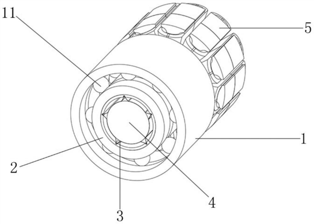
[0024] Such as figure 1 Shown: an active shaft-type combined air bearing, including an outer bearing seat 1, an inner bearing seat 2, a roller shaft 4 and several balls 11, each ball is located between the outer bearing seat and the outer ball bearing seat 21, and the inner air shaft A foil ring 3 is provided on the inner wall of the seat 22 , and the roller 4 is inside the foil ring 3 .

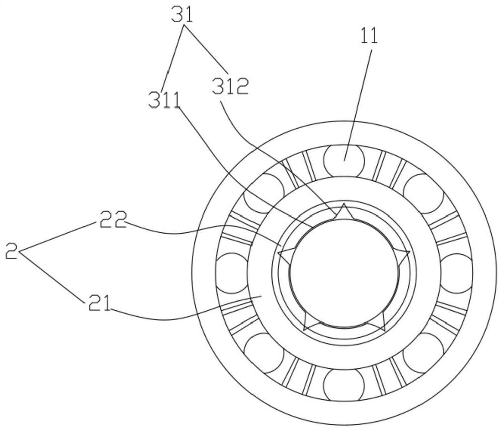
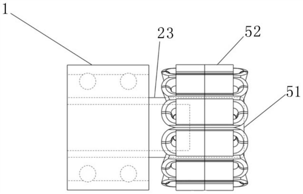
[0025] Such as figure 2 As shown: the inner bearing seat 2 includes an outer ball shaft seat 21, an inner air shaft seat 22 and an extended coaxial seat 23, and the outer ball shaft seat 21, the inner air shaft seat 22 and the extended coaxial seat 23 are integrally formed. The foil ring 3 is composed of five independent rigid foils 31 connected end to end in sequence, and the independent rigid foils 31 include arc-shaped rigid bearing parts 311 and elastically deformable pin parts 312 . The independent rigid foil has a good deformation space after being excited by the outside. The shape ...


PUM


Abstract

The invention discloses an active shaft type combined air bearing which comprises an outer bearing seat, an inner bearing seat, a rolling shaft and a plurality of balls. The inner bearing seat comprises an outer ball shaft seat, an inner air shaft seat and an extension coaxial seat, and one end of the extension coaxial seat is connected with a driving motor. When the rolling shaft starts to rotate, the driving motor starts to rotate, but the rotating direction of the driving motor is opposite to the rotating direction of the rolling shaft, so that the relative rotating speed of takeoff of the rolling shaft is increased, and the rolling shaft in a foil ring takes off faster at a lower rotating speed. When the rotating speed is gradually increased after the rolling shaft takes off, the driving motor gradually decelerates and reversely rotates, and the relative rotating speed between the rolling shaft and the inner bearing seat is reduced. The actual relative rotating speed of a rotating shaft relative to the inner bearing seat is obtained by subtracting the same-direction rotating speed of the inner bearing seat from the original highest rotating speed of the rotating shaft. Relative friction and heating between the rotating shaft and the inner bearing seat are reduced, the abrasion loss is reduced, the service life of the whole product is prolonged, and the quality of the whole product is improved.

Description

technical field [0001] The invention relates to the technical field of using foil bearings, in particular to an active shaft type combined air bearing. Background technique [0002] Air bearings are widely used in industrial fields. The higher the speed of conventional mechanical contact rolling bearings, the higher the requirements for bearing precision and lubrication, and the shorter the service life. The air bearing suspends the spindle in the air without mechanical contact, and uses clean air as the lubricant to minimize wear, so it can provide extremely high radial and axial rotation accuracy. Low temperature and radiation occasions show unique advantages. [0003] However, the take-off speed and maximum speed of air bearings in different application conditions are challenges to be faced. The higher the take-off speed, the higher the probability of contact wear between the foil and the shaft. Similarly, the higher the maximum speed, the higher the bearing friction ...

Claims


Application Information

Patent Timeline
Patent Type & Authority Applications(China)
IPC IPC(8): F16C21/00F16C17/24F16C41/00
CPCF16C17/243F16C17/246F16C21/00F16C41/004
Inventor 王乐鑫白江涛张学锋宋节季
Owner XECA TURBO TECH (BEIJING) CO LTD
Why Eureka
Try Eureka