
Water valve assembling equipment

A technology for assembling equipment and water valves, applied in metal processing equipment, assembly machines, metal processing and other directions, can solve the problems of difficult assembly, high labor cost, small space, etc., to avoid missing or wrong installation, and improve assembly efficiency. Effect

Pending Publication Date: 2021-04-23
杭州中久自控系统有限公司
View PDF0 Cites 1 Cited by
  • Summary
  • Abstract
  • Description
  • Claims
  • Application Information

AI Technical Summary

Problems solved by technology

[0002] Water valve is an important part of liquid flow control in pipelines. With the rapid development of cities and industries, water valves are widely used in urban pipelines, household pipelines and industrial pipelines, so that the scope of application is expanded and the demand is increased. The structure of the water valve includes a control head and a valve body. The control head is a component that controls the movement of the valve core inside the valve body, and the valve body is a component connected to the pipeline. The present invention relates to the assembly of the valve body and The integrated assembly equipment of the control head. The current production method of the water valve body still adopts the previous manual assembly line assembly. Since the valve body includes the shell, the valve core, the sub-block, the rear bracket and the control head, the sub-block in the valve body It is difficult to assemble the block and valve core due to the small internal space of the shell, and it is necessary to assemble sealing rings and special-shaped gaskets on multiple parts in the assembly process. There are many assembly processes, so manual assembly line manual assembly has low assembly efficiency, A series of problems such as high labor cost and low yield

Method used


Image

  • Water valve assembling equipment
  • Water valve assembling equipment
  • Water valve assembling equipment

Examples


Embodiment Construction

[0040] The following will clearly and completely describe the technical solutions in the embodiments of the present invention with reference to the accompanying drawings in the embodiments of the present invention. Obviously, the described embodiments are only some, not all, embodiments of the present invention. Based on the embodiments of the present invention, all other embodiments obtained by persons of ordinary skill in the art without making creative efforts belong to the protection scope of the present invention.

[0041] It should be noted that when a component is said to be "fixed" to another component, it can be directly on the other component or there can also be an intervening component. When a component is said to be "connected" to another component, it may be directly connected to the other component or there may be intervening components at the same time. When a component is said to be "set on" another component, it may be set directly on the other component or t...


PUM


Abstract

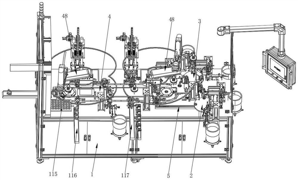
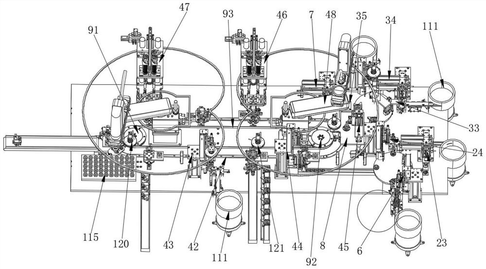
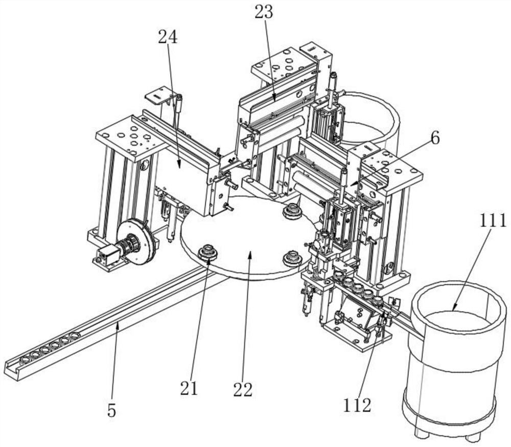
The invention innovatively provides water valve assembling equipment. The water valve assembling equipment comprises a rack, the rack comprises a first assembling area, a second assembling area and a third assembling area, wherein the first assembling area comprises a first rotating disc for bearing a first assembling station, and a special-shaped gasket assembling mechanism and a blocking block sealing ring assembling mechanism which are arranged around the first rotating disc; the second assembling area comprises a second rotating disc for bearing a second assembling station, and an end cover sealing ring assembling mechanism, an oil seal assembling mechanism and a material overturning mechanism which are arranged around the second rotating disc; and the third assembling area comprises an annular guide rail for bearing a third assembling station, a valve rod assembling mechanism, a blocking block assembling mechanism, a valve element assembling mechanism, a first locking mechanism, a second locking mechanism, a clamping manipulator located in the annular guide rail, and a transmission assembly for driving the third assembling station to slide on the annular guide rail, wherein the valve rod assembling mechanism, the blocking block assembling mechanism, the valve element assembling mechanism, the first locking mechanism and the second locking mechanism are arranged around the annular guide rail. The water valve assembling equipment has the advantage that high-efficiency automation replaces manual assembly line type production and processing of the water valve.

Description

technical field [0001] The invention relates to the technical field of water valve production and processing equipment, and more specifically relates to a water valve assembly equipment. Background technique [0002] Water valve is an important part of liquid flow control in pipelines. With the rapid development of cities and industries, water valves are widely used in urban pipelines, household pipelines and industrial pipelines, so that the scope of application is expanded and the demand is increased. The structure of the water valve includes a control head and a valve body. The control head is a component that controls the movement of the valve core inside the valve body. The valve body is a component connected to the pipeline. The present invention relates to the assembly of the valve body and The integrated assembly equipment of the control head. The current production method of the water valve body still adopts the manual assembly line assembly in the past. Since the v...

Claims


Application Information

Patent Timeline
IPC IPC(8): B23P21/00
CPCB23P19/001B23P19/007B23P21/006
Inventor 蒋庆叶晓彪
Owner 杭州中久自控系统有限公司
Learn More