
Optical fiber exchange box for communication engineering

A technology of communication engineering and switching boxes, applied in the direction of fiber mechanical structure, etc., can solve the problems of inconvenient line arrangement, easy to be affected by moisture, confusion and other problems of optical fiber switching boxes, and achieve the effect of avoiding internal moisture, avoiding moisture, and simple structure

Inactive Publication Date: 2021-04-20
梁海兮
View PDF1 Cites 0 Cited by
  • Summary
  • Abstract
  • Description
  • Claims
  • Application Information

AI Technical Summary

Problems solved by technology

[0004] The purpose of the present invention is to solve the disadvantages that the existing optical fiber exchange box is still inconvenient for line arrangement, easy to cause confusion, placed on the ground for a long time, and easy to be affected by moisture, and proposes a fiber optic exchange box for communication engineering

Method used


Image

  • Optical fiber exchange box for communication engineering
  • Optical fiber exchange box for communication engineering
  • Optical fiber exchange box for communication engineering

Examples


Embodiment 1

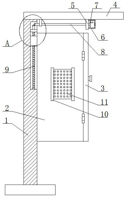
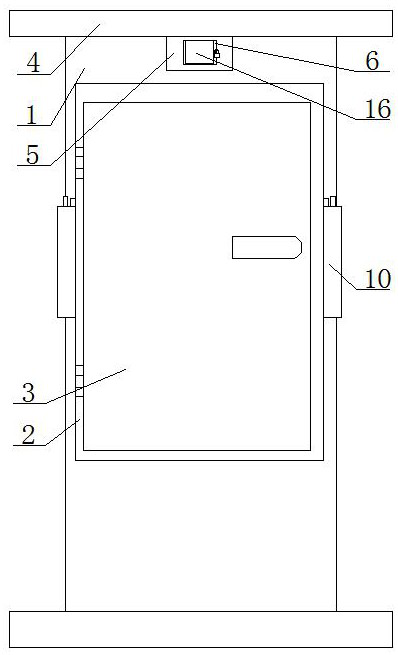
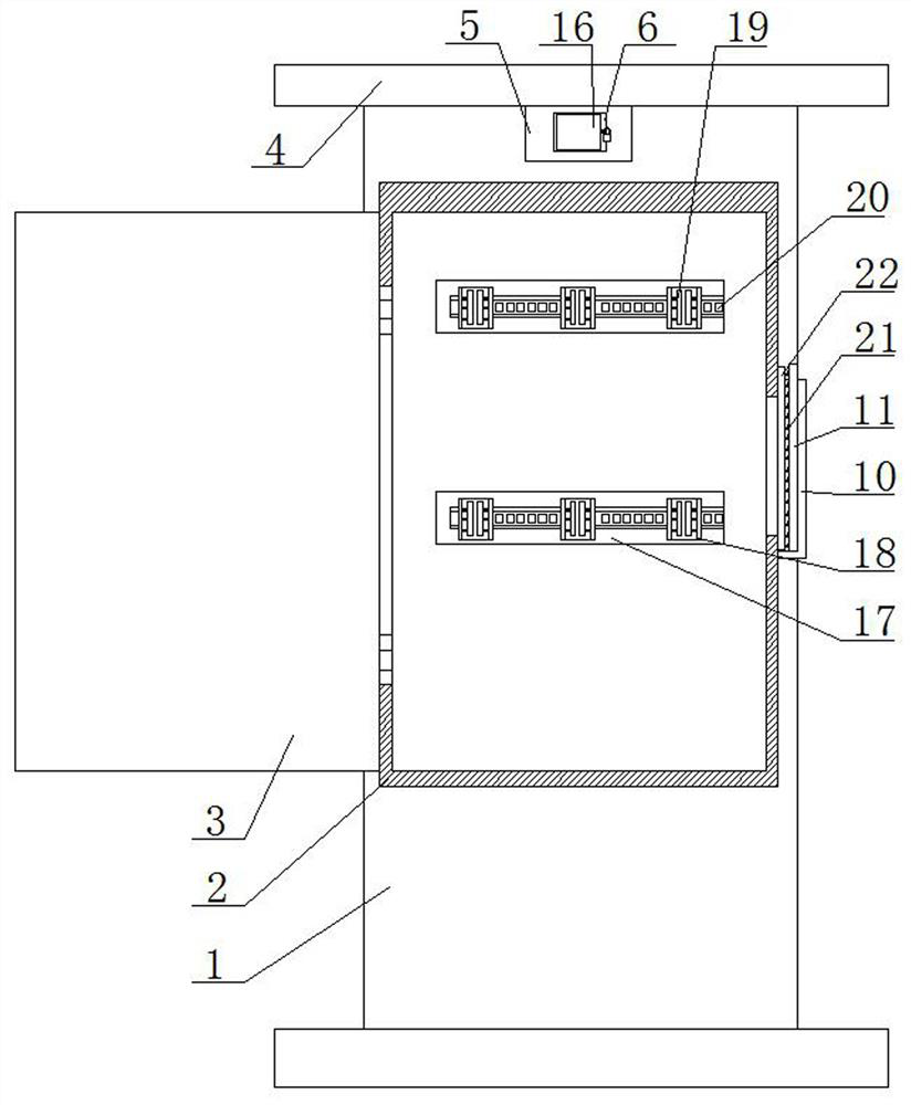
[0032] refer to Figure 1-7 , an optical fiber switching box for communication engineering, comprising a riser 1 and a switch box body 2, the switch box body 2 is slidably connected to the riser 1, a box cover 3 is rotatably installed on the switch box body 2, and both sides of the switch box body 2 Both are provided with a dust-proof structure, and the inner wall of the exchange box body 2 is provided with two support bars 17, and the tops of the two support bars 17 are provided with a top opening groove 23 with an opening on one side, and both top opening grooves 23 slide A plurality of top opening blocks 24 are installed, and the top of the top opening block 24 is connected with a U-shaped plate 18, and two arc-shaped plates 19 are symmetrically slid on the inner wall of the bottom of the U-shaped plate 18, and the outer sides of the arc-shaped plates 19 are fixed by welding One end of the spring 25 is installed, and the other end of the spring 25 is fixedly installed with ...

Embodiment 2

[0043] refer to Figure 1-7 , an optical fiber exchange box for communication engineering, comprising a riser 1 and a switch box body 2, the switch box body 2 is slidably connected to the riser 1, a box cover 3 is rotatably installed on the switch box body 2, and both sides of the switch box body 2 Both are provided with a dust-proof structure, and the inner wall of the exchange box body 2 is provided with two support strips 17, and the tops of the two support strips 17 are provided with a top opening groove 23 with an opening on one side, and both top opening grooves 23 slide A plurality of top opening blocks 24 are installed, and the top of top opening block 24 is connected with U-shaped plate 18, and two arc-shaped plates 19 are installed symmetrically on the bottom inner wall of U-shaped plate 18, and the outside of arc-shaped plate 19 is fixedly installed with One end of spring 25, the other end of spring 25 is fixedly installed with the inner wall of U-shaped plate 18.

...


PUM


Abstract

The invention belongs to the technical field of optical fiber exchange boxes, particularly relates to an optical fiber exchange box for communication engineering, and aims to solve the problems that an existing optical fiber exchange box is still inconvenient for line arrangement, easy to cause disorder, easy to be placed on the ground for a long time and easy to be affected with damp. The optical fiber exchange box comprises a vertical plate and an exchange box body which is in sliding connection with the vertical plate. A box cover is rotatably mounted on the exchange box body, dustproof structures are arranged on the two sides of the exchange box body, two supporting strips are arranged on the inner wall of the exchange box body, top opening grooves with openings in one sides are formed in the tops of the two supporting strips, and a plurality of top opening blocks are slidably mounted in the two top opening grooves. The top of the top opening block is connected with a U-shaped plate, and two arc-shaped plates are symmetrically installed on the inner wall of the bottom of the U-shaped plate in a sliding mode. According to the exchange box convenient to arrange, the structure is simple, circuit arrangement is facilitated, disorder is avoided, the height of the exchange box body can be adjusted, and the situation that the exchange box body is affected with damp on the ground is avoided.

Description

technical field [0001] The invention relates to the technical field of optical fiber switching boxes, in particular to an optical fiber switching box for communication engineering. Background technique [0002] The optical fiber switch box is a handover device that provides optical cable termination and jumper for the backbone layer optical cable and the distribution layer optical cable. At present, the optical fiber switch box used in communication engineering is mostly installed outdoors, and the working environment is harsh and vulnerable to various factors. Affecting the performance of interference equipment, Chinese patent application number: 201721506886.2, authorized announcement number: CN207318811U, provides an optical fiber switching box for communication engineering, including a box body and a box cover. This utility model uses the cooling liquid in the copper tube to absorb heat. Good heat dissipation. [0003] The existing optical fiber exchange box is still in...

Claims


Application Information

Patent Timeline
Patent Type & Authority Applications(China)
IPC IPC(8): G02B6/44
Inventor 梁海兮
Owner 梁海兮
Learn More