Method for realizing high-rise deflection monitoring based on laser spot center positioning mode

A center positioning and laser spot technology, applied in the field of measurement, can solve the problems of high cost of intelligent total stations, wide sources of GPS data errors, and difficult data processing

Active Publication Date: 2021-04-20
CHINA SHENHUA ENERGY CO LTD +2
View PDF7 Cites 0 Cited by
  • Summary
  • Abstract
  • Description
  • Claims
  • Application Information

AI Technical Summary

Problems solved by technology

Although the above methods can achieve certain goals, the accelerometer is prone to zero drift, and it is difficult to realize the quasi-static displacement monitoring. Using the inclinometer to measure requires mul

Method used


Image

  • Method for realizing high-rise deflection monitoring based on laser spot center positioning mode
  • Method for realizing high-rise deflection monitoring based on laser spot center positioning mode
  • Method for realizing high-rise deflection monitoring based on laser spot center positioning mode

Examples


Embodiment 1

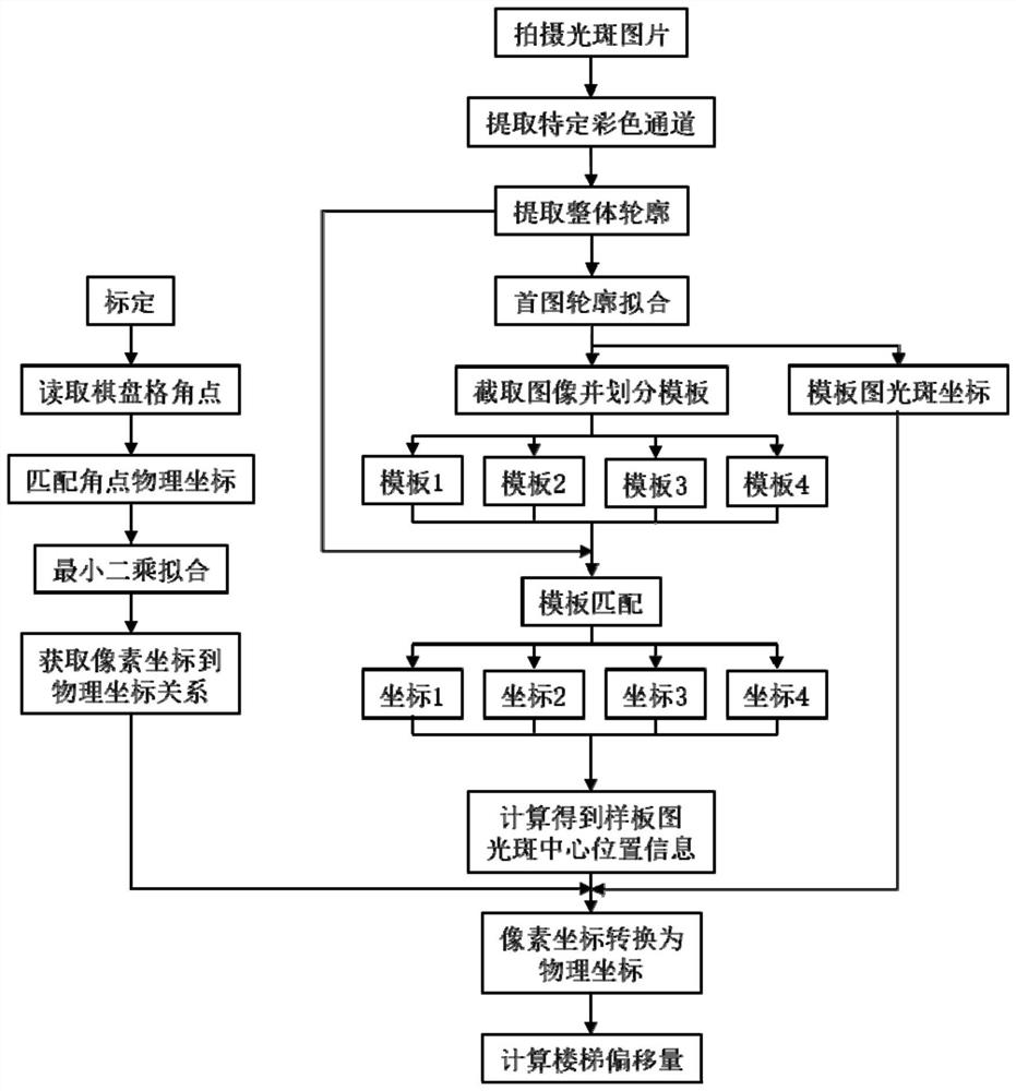
[0046] see Figure 1-3 , a method for realizing high-rise deflection monitoring based on a laser spot center positioning method, comprising the following steps:

[0047] S1. Calibrate the camera 1 in the image acquisition system. The calibration process includes the following steps:

[0048] (1) Fix camera 1, fix a checkerboard target on the side facing camera 1, adjust the focus of camera 1 until camera 1 can clearly capture the target pattern;

[0049] (2) read the pixel coordinates of the corner points of the checkerboard;

[0050] (3) Take any corner point on the checkerboard as the coordinate origin, and obtain the two-dimensional physical coordinates of the corner point on the checkerboard plane;

[0051] (4) Use the least square method to carry out polynomial fitting to obtain the mapping relationship from pixel coordinates to physical coordinates;

[0052] S2. Remove the checkerboard target, and install the light screen 2, that is, the translucent acrylic board, on ...

Embodiment 2

[0075] Such as figure 1 As shown, the displacement monitoring device of the present invention is composed of a camera 1, a laser 3 and an optical screen 2 to form an image acquisition unit, and realizes the conversion of the network cable 6-optical fiber 7-network cable 6 through the optical fiber 7 receiver 4 and the optical fiber 7 transmitter, and completes image acquisition from end-to-end transmission. Although the building body may form a certain deflection when it is swaying, the central position of the light spot captured by the camera 1 will not change with the change of the building body deflection. At the same time, since the variation of the deflection is small, it will not affect the imaging of the spot captured by the camera 1 , so for this measurement method, the variation of the deflection can basically be ignored and not recorded.

[0076] Such as figure 2 As shown, the structure of the present invention is: the laser light emitted by the laser 3 is receive...


PUM


Abstract

The invention discloses a method for realizing high-rise deflection monitoring based on a laser spot center positioning mode. The method comprises the following steps: S1, calibrating a camera in an image acquisition system; S2, dismounting a checkerboard target, and mounting an optical screen, namely, a semitransparent acrylic plate, at a high position of a to-be-detected building; S3, capturing pictures with light spot position information in real time on the side, far away from the laser, of the acrylic plate by the camera, and transmitting the pictures to a computer terminal; and S4, the computer terminal analyzes the obtained pictures with the light spots. According to the invention, the laser, the CMOS camera, contour fitting and a template matching algorithm are combined to develop an online detection scheme of high-rise building deflection, and high-precision monitoring of high-rise building deflection is realized by utilizing the characteristic that the laser propagates along a straight line.

Description

technical field [0001] The present application relates to the field of measurement technology, and in particular to a method for realizing deflection monitoring of tall buildings based on laser spot center positioning. Background technique [0002] With the strengthening of economic strength, there are more and more high-rise buildings. High-rise buildings will undergo vibration deformation and slow pseudo-static deformation under the influence of external factors such as loads, strong winds, and temperature changes. The amount of deformation directly affects their safety and health. Evaluating the health status of high-rise buildings and avoiding catastrophic accidents is of great significance to the assessment of building safety operation capabilities, structural design parameter inspection, and building life assessment. [0003] At present, conventional sensors for vibration and deformation monitoring of high-rise buildings mainly include accelerometers, inclinometers, a...

Claims


Application Information

Patent Timeline
IPC IPC(8): G01B11/00G01B11/02
Inventor 刘建海王树民宋畅李延兵张军亮梁添刘龙崔健
Owner CHINA SHENHUA ENERGY CO LTD
Why Eureka
Try Eureka