
Illuminating lamp convenient for adjusting illuminating range

A technology of irradiation range and lighting lamps, which is applied in the direction of lighting devices, fixed lighting devices, lighting auxiliary devices, etc., can solve the problems of scrapping, low safety factor, falling lighting lamps, etc., so as to improve safety factor, service life and improve The effect of practicality

Inactive Publication Date: 2021-04-20
胡德臻
View PDF0 Cites 0 Cited by
  • Summary
  • Abstract
  • Description
  • Claims
  • Application Information

AI Technical Summary

Problems solved by technology

[0002] The lighting is used to identify objects in a dark environment. The types of lighting are divided according to the use of the lighting. The distance of the lighting is also different. The range of the existing lighting is fixed. When it is necessary to illuminate different positions , you need to shake the lighting back and forth, there will be a dead angle of lighting, which is not conducive to observation, and the safety factor is low
[0003] When the existing lighting lamp changes the lighting range, it is necessary to shake the lighting lamp to expand the irradiation range, but shaking the lighting lamp back and forth will make it difficult to see the road at night, resulting in a decrease in the illumination effect, resulting in a reduction in the safety factor of night driving, and at the same time The fall of the lighting lamp causes the lighting lamp to be damaged or even scrapped, which reduces the service life of the lighting lamp and causes a waste of resources

Method used


Image

  • Illuminating lamp convenient for adjusting illuminating range
  • Illuminating lamp convenient for adjusting illuminating range
  • Illuminating lamp convenient for adjusting illuminating range

Examples


Embodiment Construction

[0025] The following will clearly and completely describe the technical solutions in the embodiments of the present invention with reference to the accompanying drawings in the embodiments of the present invention. Obviously, the described embodiments are only some, not all, embodiments of the present invention. Based on the embodiments of the present invention, all other embodiments obtained by persons of ordinary skill in the art without making creative efforts belong to the protection scope of the present invention.

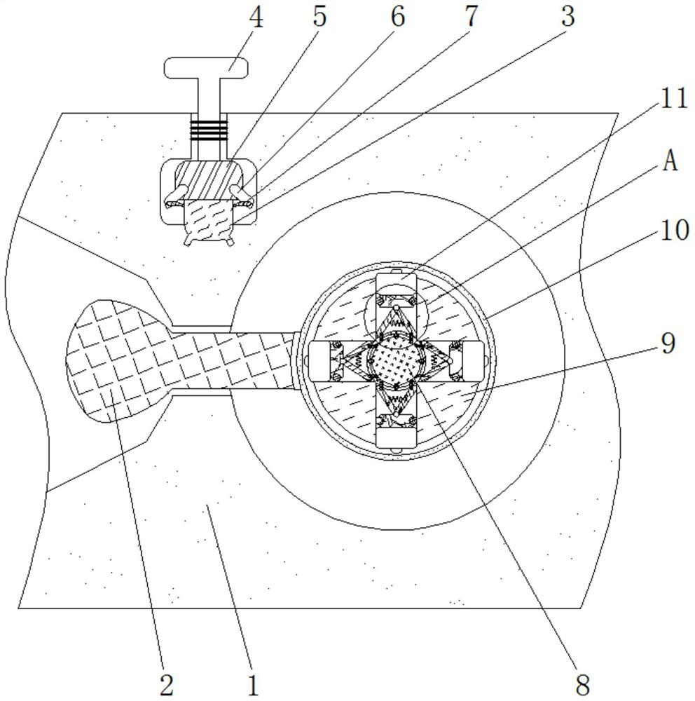
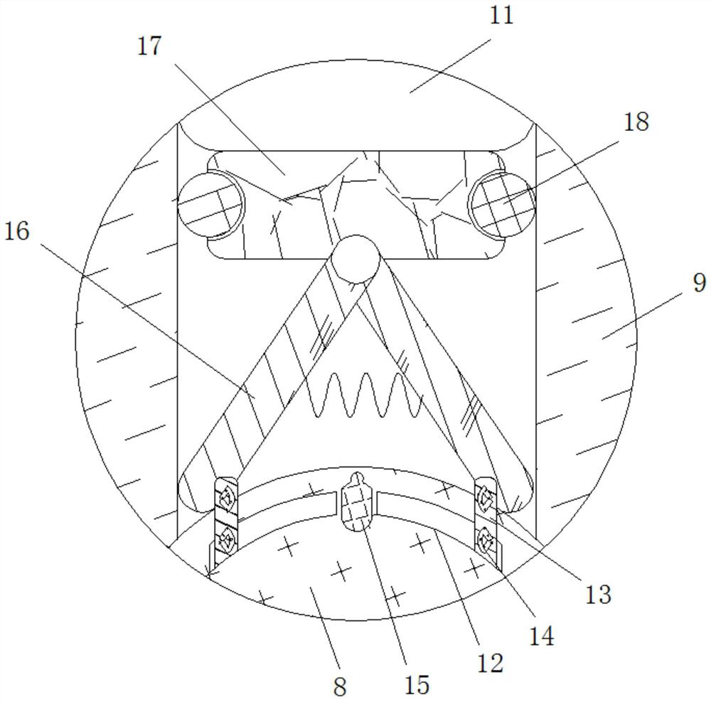
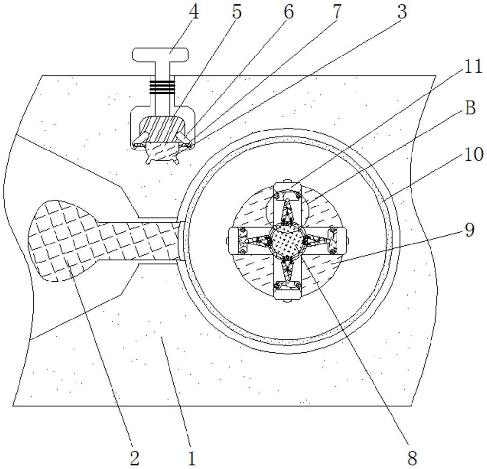
[0026] see Figure 1-4 , an illuminating lamp for adjusting the irradiation range, comprising a housing 1, the inner wall of the housing 1 is movably connected with a lamp cap 2, the inner wall of the housing 1 is fixedly connected with a sliding rheostat 3, and the inner wall of the housing 1 is threadedly connected with a screw rod 4, The bottom of the screw rod 4 is fixedly connected with a slider 5, which is threadedly connected with the sliding rheostat 3...


PUM


Abstract

The invention relates to the technical field of lighting devices, and discloses an illuminating lamp convenient for adjusting illuminating range. The illuminating lamp comprises a shell, the inner wall of the shell is movably connected with a lamp holder, the inner wall of the shell is fixedly connected with a slide rheostat, the inner wall of the shell is in threaded connection with a screw rod, the bottom of the screw rod is fixedly connected with a slide block, a connecting rod is fixedly connected to the outer side of the slide block, a contact piece is fixedly connected to the inner side of the connecting rod, a connecting roller is fixedly connected to the inner wall of the shell, and a leather collar is movably connected to the positions, close to the outer side of the connecting roller, of the inner wall of the shell. According to the illuminating lamp convenient for adjusting illuminating range, by changing the resistance value of the slide rheostat, the situation that a night road cannot be seen clearly due to back-and-forth shaking of illuminating lamps is avoided, the illuminating effect is improved, the safety coefficient of night walking is increased, meanwhile, the illuminating lamps are prevented from falling off, damage or even scrapping of the illuminating lamp is avoided, the service life of the illuminating lamps is prolonged, and resources are saved.

Description

technical field [0001] The invention relates to the technical field of illuminating devices, in particular to an illuminating lamp which is convenient for adjusting the irradiation range. Background technique [0002] The lighting is used to identify objects in a dark environment. The types of lighting are divided according to the use of the lighting. The distance of the lighting is also different. The range of the existing lighting is fixed. When it is necessary to illuminate different positions , It is necessary to shake the lighting back and forth, and there will be a dead angle of lighting, which is not conducive to observation, and the safety factor is low. [0003] When the existing lighting lamp changes the lighting range, it is necessary to shake the lighting lamp to expand the irradiation range, but shaking the lighting lamp back and forth will make it difficult to see the road at night, resulting in a decrease in the illumination effect, resulting in a reduction in...

Claims


Application Information

Patent Timeline
Patent Type & Authority Applications(China)
IPC IPC(8): F21S8/00F21V21/15
Inventor 胡德臻
Owner 胡德臻
Learn More