Frost heaving prevention uplift device for telegraph pole in frozen soil area

A technology for utility poles and anti-frost heave, applied in protection devices, building types, buildings, etc., can solve the problems of falling poles, high manpower and material costs, and failure of utility poles to fall back normally, so as to increase the pull-up resistance and reduce maintenance. The effect of frequency and cost

Pending Publication Date: 2021-04-20
徐州华显凯星信息科技有限公司
View PDF9 Cites 2 Cited by
  • Summary
  • Abstract
  • Description
  • Claims
  • Application Information

AI Technical Summary

Problems solved by technology

[0002] The utility poles erected in the environment with severe soil frost heaving in the permafrost area will be pulled up due to the soil frost heaving problem, because when the thickness of the permafrost layer reaches a certain threshold, the bonding force between the permafrost and the utility poles will increase. It is greater than the total weight of the utility pole shaft, which causes the soil on the utility pole to be lifted up with frost heave, causing a cavity area to appear at the bottom of the utility pole, and the cavity area that appears will be filled by the surrounding unfrozen soil and sand , As a result, when the permafrost thaws, the utility poles cannot fall back normally, which leads to the gradual uplifting of the utility poles, and finally the phenomenon of downturning. The traditional treatment method is to manually excavate and backfill every year, and the overall consumption The cost of manpower and material resources is high, and in the prior art, the problem of backfilling the cavity is solved by placing a sleeve on the outside of the pole insertion part. The ring cover of this device can only drain the sand body to the surrounding, but it does not Completely isolate the unfrozen layer sand body from the hole pulled up by the utility pole, and the unfrozen layer sand body still has the possibility of falling back into the hole
[0003] Notification No. CN108643680A discloses a structure for preventing the uplifting of utility poles caused by soil frost heave. The structure for preventing the uplifting of utility poles caused by soil frost heaving includes: utility poles, sleeves, waterproof layers, and drag-reducing layers; The sleeve is set at the bottom of the utility pole; the sleeve and the utility pole are set in the waterproof layer; the drag reducing layer is set on the surface of the root of the utility pole; the sleeve is composed of a cylinder body and a ring cover, and the cylinder body It is fixedly connected with the ring cover; the upper end of the ring cover is connected with the utility pole at an acute angle, and the upper end of the ring cover is fixedly connected with the utility pole; the lower edge of the cylinder is blade-shaped; the inside of the sleeve, The gap between the sleeve and the waterproof layer is filled with dry and compacted fine sand. This device cannot completely isolate the unfreezing layer of sand from the cavity under the utility pole when the utility pole is pulled up, and the cavity is still in danger of being filled.
[0004] Notification number CN108589760A discloses a structure with a reset function to prevent the pull-out of a power transmission pole, including: a pole, a drag-reducing layer, a ring cover, and a reset device; Pull out the hole on the pole to isolate it, and the sand is easy to fill near the tire and the ring cover, so that the pole cannot fall back

Method used


Image

  • Frost heaving prevention uplift device for telegraph pole in frozen soil area
  • Frost heaving prevention uplift device for telegraph pole in frozen soil area

Examples


Embodiment 1

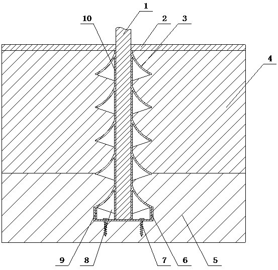
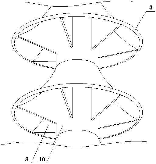
[0024] An anti-frost heave lifting device for electric poles in permafrost regions of the present invention is realized in the following way: an anti-frost heaving and upward pulling device for electric poles in permafrost regions of the present invention is composed of a bottom fixing structure and a side wing expansion structure, and the bottom fixing structure is composed of a fixing seat ( 6) and screw fixing inserts (7), a plurality of screw fixing inserts (7) are placed on the fixing seat (6), the fixing seat (6) is a cylinder with one end sealed, and the side wing expansion structure is blocked by Umbrella plate (3), reinforcing ribs (8), slider (9) and sleeve (10), a plurality of barrier umbrella plates (3) are equidistantly placed on the sleeve (10), the barrier umbrella plate (3) A reinforcing rib (8) is provided between the sleeve (10), and the reinforcing rib (8) is equiangularly distributed under the umbrella skirt of the barrier umbrella (3), and the reinforcing r...

Embodiment 2

[0030] The difference between this embodiment and Embodiment 1 is: the tip of the bolt-fixing nail body is smooth, and the middle part is provided with threads; when in use, the guiding performance of the bolt-fixing nail can be improved, and screw fastening can be performed in combination with the spiral in the middle , to improve the fixing strength of the fixing seat (6).

Embodiment 3

[0032] The difference between this embodiment and Embodiment 1 is: the edge of the shed of the barrier umbrella plate (3) is provided with corrugated folds; when in use, it can be embedded with the backfilled soil to increase the combined area.


PUM


Abstract

The invention relates to a frost heaving prevention uplift device for a telegraph pole in a frozen soil area, and discloses the frost heaving prevention uplift device which can be combined with a permafrost heaving layer for filling, support and fix the telegraph pole and avoid uplifting. The frost heaving prevention uplift device is characterized in that a bottom fixing structure is composed of a fixing seat and a plurality of spiral fixing plug pins; the spiral fixing plug pins are arranged on the fixing seat; the fixing base is a cylinder with one end sealed; a plurality of blocking umbrella plates are arranged on a sleeve at equal intervals; reinforcing ribs are arranged between the blocking umbrella plates and the sleeve; the reinforcing ribs are distributed below umbrella skirts of the blocking umbrella plates at equal angles; the reinforcing ribs are made of hard plastic; the edge of the blocking umbrella plate at the bottommost end is provided with a sliding cylinder; and the sliding cylinder is inserted into the fixing seat in a sleeved mode and is in close fit with the fixing seat.

Description

technical field [0001] The invention relates to an anti-frost heaving and pulling up device for utility poles in permafrost regions, which relates to a branch for installing utility poles in permafrost regions to avoid uplifting loading, and belongs to the field of electric power engineering. In particular, it relates to an anti-frost heaving uplifting device that can be combined with heaving soil layers for filling, and supports and fixes utility poles to avoid uplifting. Background technique [0002] The utility poles erected in the environment with severe soil frost heaving in the permafrost area will be pulled up due to the soil frost heaving problem, because when the thickness of the permafrost layer reaches a certain threshold, the bonding force between the permafrost and the utility poles will increase. It is greater than the total weight of the utility pole shaft, which causes the soil on the utility pole to be lifted up with frost heave, causing a cavity area to app...

Claims


Application Information

Patent Timeline
Patent Type & Authority Applications(China)
IPC IPC(8): E02D31/14E02D27/42E04H12/22
Inventor 不公告发明人
Owner 徐州华显凯星信息科技有限公司
Why Eureka
Try Eureka