Road surface marking cleaning equipment for road

A technology for road marking and cleaning equipment, applied in road cleaning, cleaning methods, electromagnetic audible signals, etc., can solve problems such as easily overlooked water volume problems

Active Publication Date: 2021-04-20
山东顺通公路工程有限公司
View PDF16 Cites 2 Cited by
  • Summary
  • Abstract
  • Description
  • Claims
  • Application Information

AI Technical Summary

Problems solved by technology

[0005] In order to overcome the shortcomings of manual cleaning in the prior art, manual removal of dirty water, repeated pouring of water, and additional manpower to remove garbage, it is easy to ignore the shortcomings of water volume. Water flows out continuously, automatically cleans garbage and automatically reminds that the water is insufficient. Road marking cleaning equipment for roads

Method used


Image

  • Road surface marking cleaning equipment for road
  • Road surface marking cleaning equipment for road
  • Road surface marking cleaning equipment for road

Examples


Embodiment 1

[0030] A road surface marking cleaning equipment for roads, such as figure 1 , figure 2 and image 3 As shown, it includes a wheel 1, a base 2, a shell 3, a cleaning mechanism 4 and a spray mechanism 5, and the front and rear sides of the bottom of the base 2 are connected with the wheel 1 in a symmetrical rotation type, and the upper part of the base 2 is connected with the shell 3, and the shell 3 is on the right. The side is provided with a cleaning mechanism 4, and the upper left side of the base 2 is provided with a spray mechanism 5.

[0031] The cleaning mechanism 4 includes a pressing rod 41, a fixed rod 42, a first connecting rod 43, a first spring 44, a second connecting rod 45, a first chute 46 and a sponge pad 47, and the upper right rear side of the casing 3 is connected with a second A connecting rod 43, the first connecting rod 43 is slidably connected with a pressing rod 41, the first spring 44 is connected between the pressing rod 41 and the shell 3, the fi...

Embodiment 2

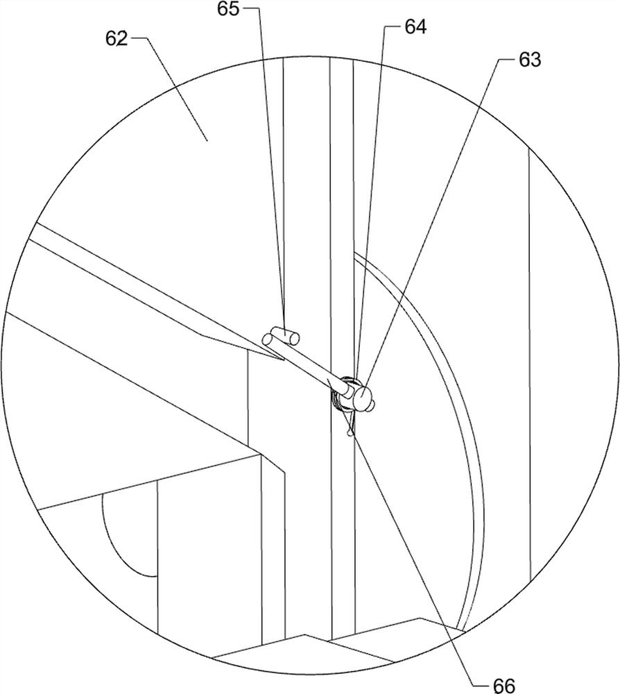
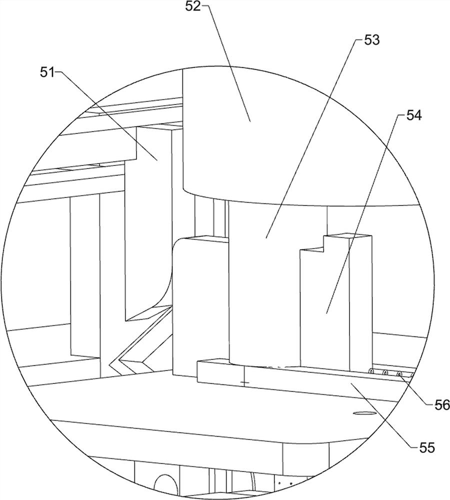
[0035] On the basis of Example 1, such as Figure 4 , Figure 5 , Figure 6 , Figure 7 and Figure 8 As shown, the extruding assembly 6 is also included, and the extruding assembly 6 includes a pressing block 61, a third chute 62, a first rotating rod 63, a torsion spring 64, a gear rod 65, a third connecting rod 66 and a sliding rod 67 , the front side of the first chute 46 is slidingly connected with a pressure block 61, the pressure block 61 cooperates with the sponge pad 47, the right side of the pressure block 61 is connected with a sliding rod 67, and the right front side of the base 2 is connected with a third chute 62, the sliding rod 67 is slidingly connected with the third chute 62, the left front side of the first chute 46 bottom is rotationally connected with the first rotating rod 63, and the left rear side of the first rotating rod 63 is connected with the third connecting rod 66, A torsion spring 64 is connected between the third connecting rod 66 and the f...


PUM


Abstract

The invention relates to cleaning equipment and particularly relates to road surface marking cleaning equipment for a road. According to the road surface marking cleaning equipment for the road, marking cleaning, automatic dirty water extrusion, simple and convenient continuous outflow of water, automatic garbage sweeping and automatic water shortage reminding are easily achieved. According to the equipment, the road surface marking cleaning equipment for the road comprises a base, a shell, a wiping mechanism and a spraying mechanism, wherein wheels are symmetrically and rotationally connected to the two sides of the bottom of the base; the upper part of the base is connected with the shell; the wiping mechanism is arranged on one side of the shell; the spraying mechanism is arranged on one side of the upper part of the base. By pulling the pressing rod to move downwards, the sponge mat is driven to move downwards to make contact with the marked line, meanwhile, the wedge-shaped block is driven to move downwards, the connecting block is pushed to move leftwards to be aligned with the opening of the supporting pipe, water is sprayed to the marked line through the spray head, and the effect of easily cleaning the marked line of the highway pavement is achieved.

Description

technical field [0001] The invention relates to a cleaning device, in particular to a cleaning device for road surface markings. Background technique [0002] Road markings for highways refer to signs on the road surface that use lines, arrows, text, facade marks, raised road signs and contour marks to convey traffic information such as guidance, restrictions, and warnings to traffic participants. It plays an important role in controlling and guiding traffic, so it is necessary to ensure that the marking lines are clean and clear, and clean the marking lines regularly. [0003] The existing pavement markings are mostly cleaned manually. After the user pours water on the markings, he uses a cleaning tool to wipe and clean the markings to restore the original appearance of the markings. This method requires manual use. It takes a lot of physical strength to wipe the marking line with tools, and the efficiency is not high. Secondly, during the cleaning process, the cleaning to...

Claims


Application Information

Patent Timeline
Patent Type & Authority Applications(China)
IPC IPC(8): E01H1/00E01H1/10E01H1/05G08B3/10G08B21/24
Inventor 黄峰
Owner 山东顺通公路工程有限公司
Why Eureka
Try Eureka