Pneumatic nailing gun

A nailing gun and pneumatic technology, applied in the direction of nailing tools, manufacturing tools, etc., can solve the problem that the nailing force is difficult to adjust

Pending Publication Date: 2021-04-20
TAIZHOU DINGBA POWER TOOLS
View PDF2 Cites 2 Cited by
  • Summary
  • Abstract
  • Description
  • Claims
  • Application Information

AI Technical Summary

Problems solved by technology

[0005] The purpose of the present invention is to solve the above problems in the existing technology, and propose a pneumatic nailing gun to solve the problem that the nailing force is difficult to adjust in order to make the unlocking of the power piston more stable and reliable in the existing pneumatic nailing gun

Method used


Image

  • Pneumatic nailing gun
  • Pneumatic nailing gun
  • Pneumatic nailing gun

Examples


Embodiment Construction

[0030] The following are specific embodiments of the present invention and in conjunction with the accompanying drawings, the technical solutions of the present invention are further described, but the present invention is not limited to these embodiments.

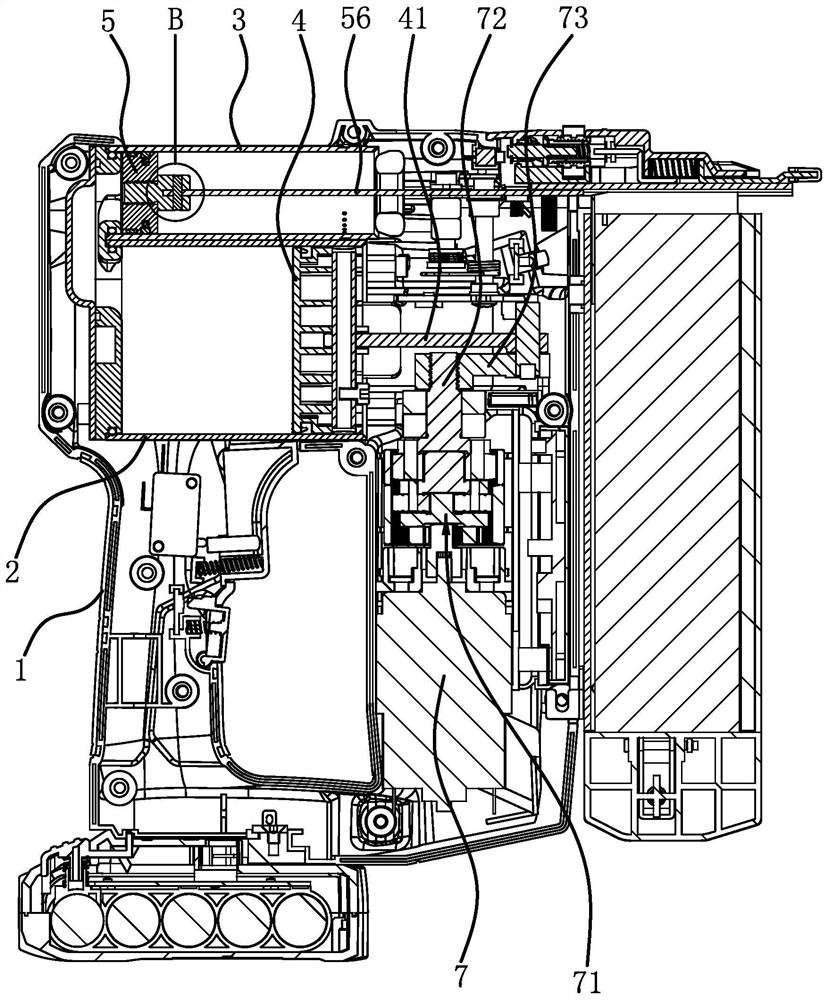
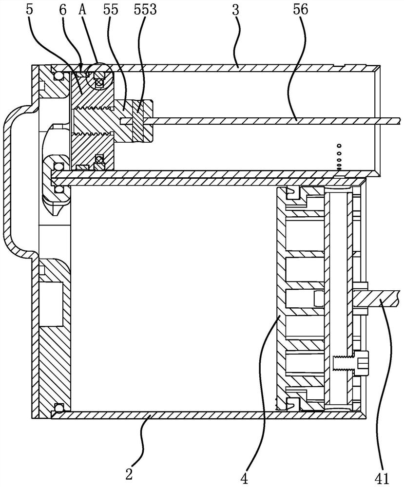
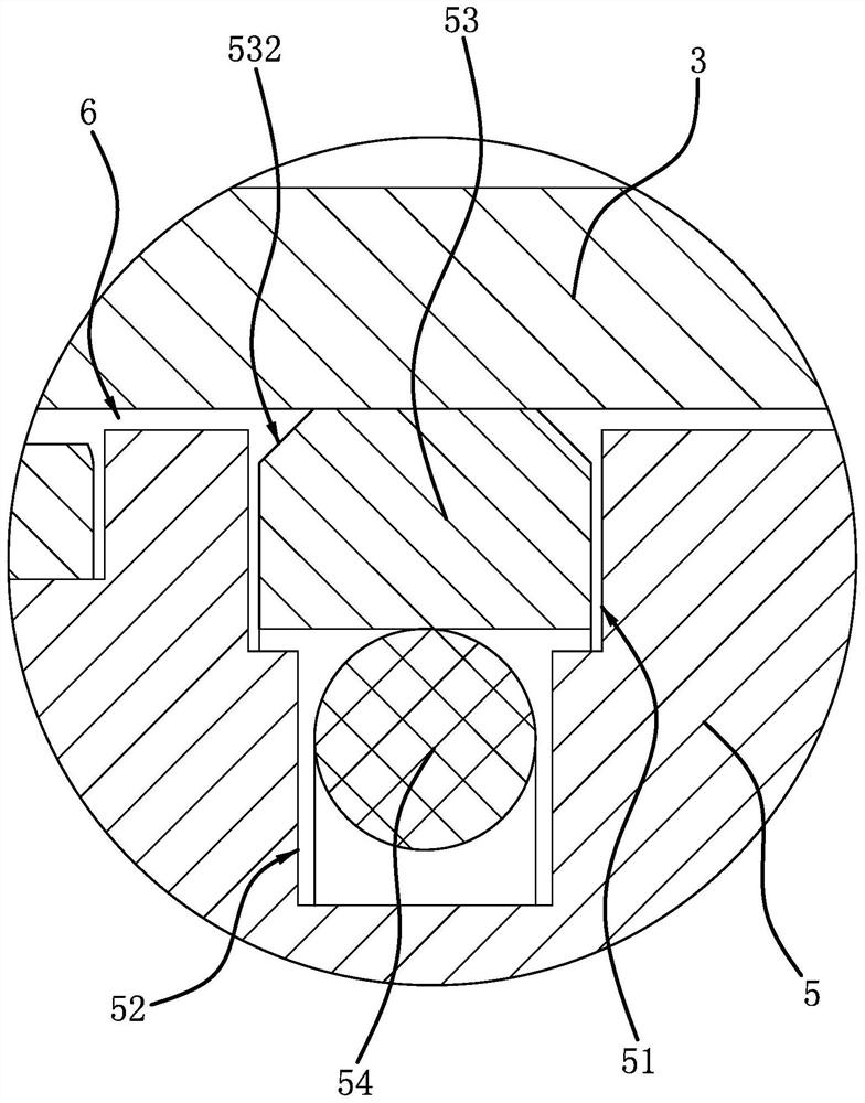
[0031] Such as figure 1 , figure 2 As shown, a pneumatic nailing gun includes a housing 1, a booster cylinder 2 and a power cylinder 3 are fixed inside the housing 1, the power cylinder 3 and the booster cylinder 2 are arranged along the front and back, and the power cylinder The body 3 is located above the booster cylinder 2, the inner cavity of the power cylinder 3 is connected with the inner cavity of the booster cylinder 2, the booster piston 4 is arranged in the booster cylinder 2, and the booster piston 4 is arranged in the power cylinder 3 There is a power piston 5, because the inner diameter of the power cylinder 3 is smaller than the inner diameter of the booster cylinder 2, and the length of the power cylinder ...


PUM


Abstract

The invention provides a pneumatic nailing gun, and belongs to the technical field of electric tools. Through the pneumatic nailing gun, the problem that in order to enable a power piston to be unlocked more stably and reliably, the nailing strength of an existing pneumatic nailing gun is difficult to adjust is solved. The pneumatic nailing gun comprises a shell, wherein a pressurizing cylinder body and a power cylinder body are arranged in the shell, a pressurizing piston is arranged in the pressurizing cylinder body, a power piston capable of being locked when the pressurizing piston pressurizes an inner cavity is arranged in the power cylinder body, a motor can unlock the power piston when the pressurizing piston completes a pressurizing stroke, a pressure relief channel is formed between the power piston and the power cylinder body, the pneumatic nailing gun further comprises a rotational speed control module capable of controlling the rotational speed of the motor, the rotational speed control module adjusts the time required for the pressurizing piston to complete the pressurizing stroke by controlling the rotational speed of the motor, and the rotational speed control module can control the motor to output at least two different rotational speeds. The pneumatic nailing gun can control the nailing strength through the rotational speed of the motor.

Description

technical field [0001] The invention belongs to the technical field of electric tools and relates to a pneumatic nail gun. Background technique [0002] The pneumatic nail gun is composed of the gun body and the nail box. The gun body is composed of the gun shell, cylinder, trigger assembly, firing pin assembly, gun nozzle and bumper assembly, etc., and the pressure difference is formed after the air is compressed by the cylinder. , through the trigger switch to make the striker reciprocate in the cylinder, usually the pneumatic nailing gun is driven by the air pressure in the power cylinder to drive the power piston, and then the steel nail is driven out, so the air pressure in the power cylinder determines the steel nail. strength. [0003] In order to ensure the accuracy of the air pressure value, and thus ensure the accuracy of the driving force of the steel nails, the patent document (application number: 201920866981.6) discloses a multi-functional air nozzle and a con...

Claims


Application Information

Patent Timeline
Patent Type & Authority Applications(China)
IPC IPC(8): B25C1/04
Inventor 张华定
Owner TAIZHOU DINGBA POWER TOOLS
Why Eureka
Try Eureka