
Control signal generation circuit and switching power supply

A technology for controlling signals and generating circuits, applied in control/regulating systems, electrical components, adjusting electrical variables, etc., to solve problems such as abnormal power supply, signal interference, and power consumption

Active Publication Date: 2021-04-16
WUXI CRYSTAL SOURCE MICROELECTRONICS CO LTD
View PDF4 Cites 0 Cited by
  • Summary
  • Abstract
  • Description
  • Claims
  • Application Information

AI Technical Summary

Problems solved by technology

[0003]When the current detection resistor Rs is working, it will inevitably consume power. The larger the resistance value, the more power consumption; if If the resistance value is too small, the current detection voltage is too low, which is easily interfered by other signals, causing misjudgment of peak current detection, and resulting in abnormal power supply

Method used


Image

  • Control signal generation circuit and switching power supply
  • Control signal generation circuit and switching power supply
  • Control signal generation circuit and switching power supply

Examples


Embodiment Construction

[0036] The implementation manner of this solution will be further described in detail below in conjunction with the accompanying drawings. Apparently, the described embodiments are only part of the embodiments of the solution, rather than exhaustive of all the embodiments. It should be noted that, in the case of no conflict, the embodiments in this solution and the features in the embodiments can be combined with each other.

[0037] The terms "first", "second", etc., if present, in the description and claims and the above drawings are used to distinguish similar items and not necessarily to describe a specific order or sequence. It is to be understood that the terms so used are interchangeable under appropriate circumstances such that the embodiments described herein can be practiced in sequences other than those illustrated or described herein. Furthermore, the terms "comprising" and "having", as well as any variations thereof, are intended to cover a non-exclusive inclusio...


PUM


Abstract

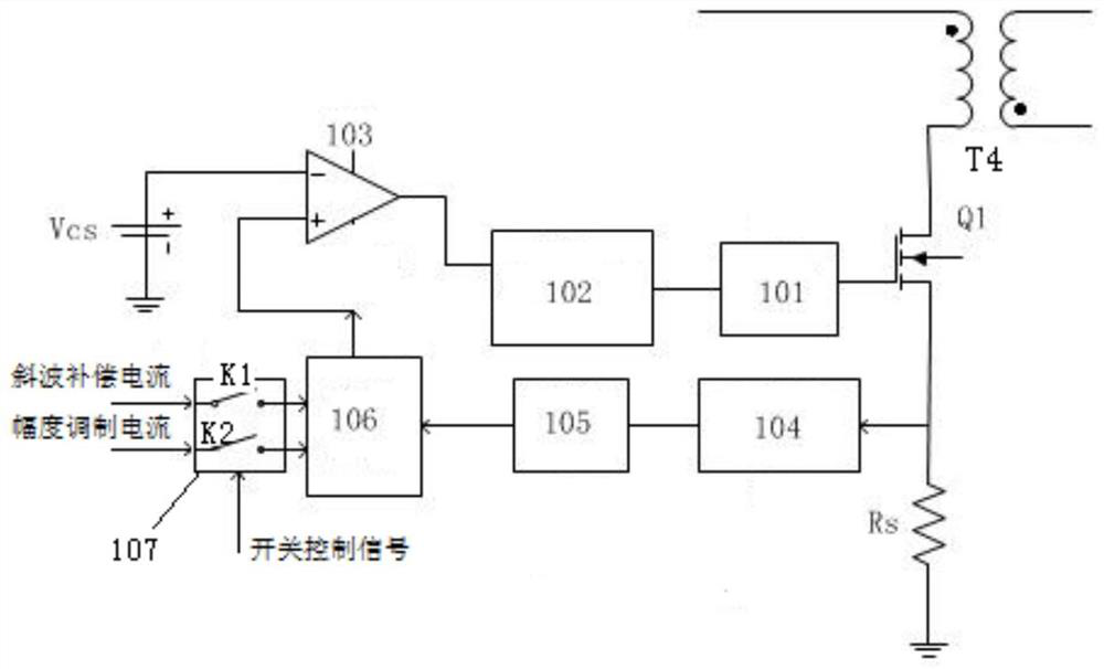
The invention discloses a control signal generation circuit. The control signal generation circuit is characterized by comprising a signal superposition unit, a switch unit, a comparator and a controller, wherein the output end of the switch unit is connected with the input end of the signal superposition unit; and the signal superposition unit superposes a preprocessed to-be-detected current signal and a first adjusting signal transmitted by the switch unit and then outputs a first comprehensive signal, or superposes the preprocessed to-be-detected current signal with a second adjusting signal transmitted by the switch unit and then outputs a second comprehensive signal. By using the circuit provided in the above scheme, the problems that peak detection voltage is easily interfered by noise and power supply output is unstable because current detection resistance is too small are solved; secondly, since the resistance value of a used current detection resistor is relatively small, the working efficiency of the power supply is improved; and in addition, all compensation function modules are gathered together, so a circuit structure is simplified.

Description

technical field [0001] The invention relates to the technical field of switching power supply current detection, in particular to a control signal generating circuit and a switching power supply. Background technique [0002] The current control of the switching power supply in the voltage-current mode is a control method in which the fixed clock is turned on and the peak current is turned off. When the current detection resistor senses that the peak current of the inductor exceeds the set value, the power switch tube of the controller will be turned off immediately to form a cycle-by-cycle current limit, so that the peak current of the power switch tube will be controlled by any transient change of the input voltage and load. The control is within a certain range, and it can effectively protect the main switch tube in case of overload and short circuit. The advantage of the peak current mode control is that the transient closed-loop response is fast, and the transient resp...

Claims


Application Information

Patent Timeline
Patent Type & Authority Applications(China)
IPC IPC(8): H02M3/335H02M1/44
Inventor 曹元
Owner WUXI CRYSTAL SOURCE MICROELECTRONICS CO LTD
Learn More