
A ring cutting device for cable processing with waste collection function

A waste collection and ring cutting technology, applied in electronic waste recycling, recycling technology, circuits, etc., can solve problems such as low efficiency and labor consumption, and achieve the effect of ensuring efficiency, improving efficiency and quality, and reasonable design

Active Publication Date: 2022-02-15
安徽维尔特仪表线缆有限公司
View PDF5 Cites 0 Cited by
  • Summary
  • Abstract
  • Description
  • Claims
  • Application Information

AI Technical Summary

Problems solved by technology

[0005] The purpose of the present invention is to solve the problem of labor-intensive and low efficiency in the prior art, and propose a ring cutting device for cable processing with waste material collection function

Method used


Image

  • A ring cutting device for cable processing with waste collection function
  • A ring cutting device for cable processing with waste collection function
  • A ring cutting device for cable processing with waste collection function

Examples


Embodiment 1

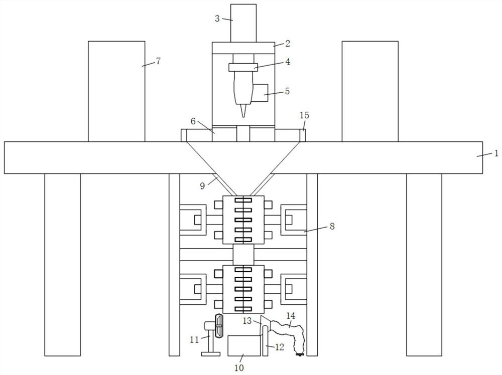
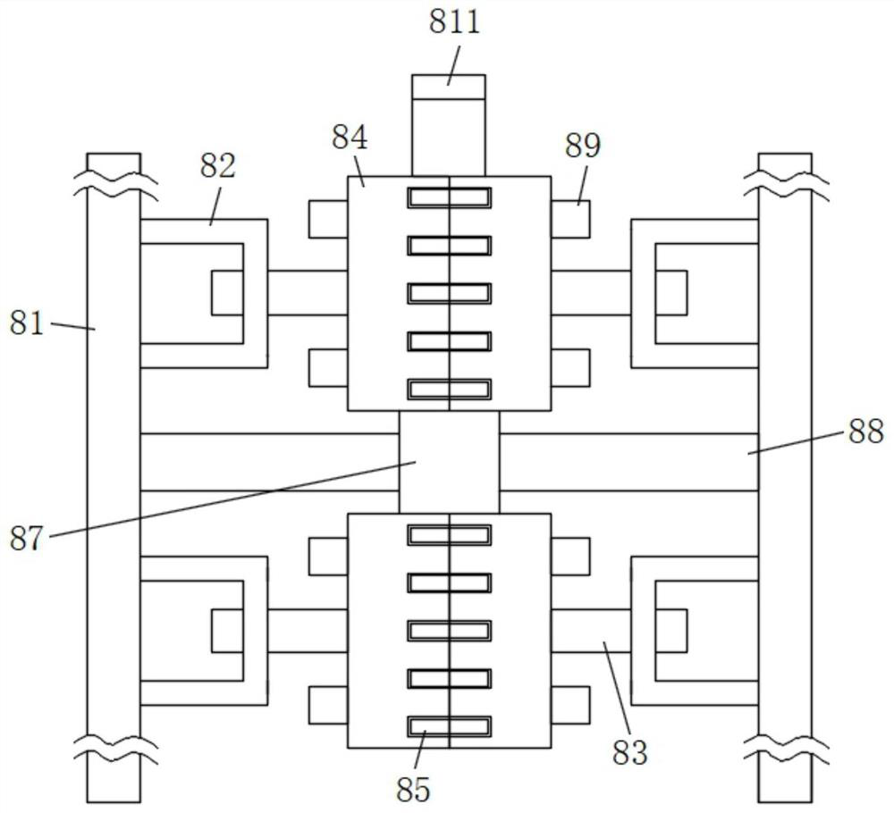
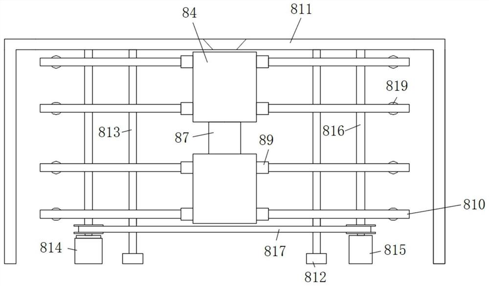
[0030] refer to Figure 1-5A circular cutting device for cable processing with a waste collection function, comprising a workbench 1, a work frame 2 is fixedly connected to the middle part of the top surface of the workbench 1, and a cylinder 3 is fixedly connected to the outer top surface of the work frame 2 through screws, and the cylinder 3 The output end passes through the top surface of the working frame 2 and is fixedly connected with a mounting block 4 at the end by screws. Both sides of the outer top surface are also fixedly connected with fixing mechanisms 7, and the middle part of the top surface of the workbench 1 is also provided with a tapered hole, and the lower side of the tapered hole is also provided with a circumcision mechanism 8. The circumcision mechanism 8 includes a mounting plate 81, two One end of the mounting plate 81 is fixedly connected with a U-shaped frame 82 by screws, and the side of the U-shaped frame 82 is slidably connected with a mounting ro...

Embodiment 2

[0033] Such as figure 1 As shown, this embodiment is basically the same as Embodiment 1. Preferably, a retaining ring 15 is fixedly connected to the inner wall of the top side of the tapered hole, and the retaining ring 15 is placed inside the working frame 2 .

[0034] In this embodiment, the retaining ring 15 is fixedly attached to the inner wall of the top side of the tapered hole, so that the cut cable section can be smoothly introduced into the material guide pan 2 9, thereby realizing the complete cutting operation of the cable section.

Embodiment 3

[0036] Such as figure 1 As shown, this embodiment is basically the same as Embodiment 1. Preferably, a discharge hole is opened through the middle of the top surface of the cutting table 6, and the lower end of the discharge hole communicates with the tapered hole.

[0037] In this embodiment, a discharge hole is connected between the top surface of the cutting table 6 and the tapered hole, so that the waste cable can smoothly fall into the material guide pan 2 after cutting.


PUM


Abstract

The invention discloses a circular cutting device for cable processing with the function of collecting waste materials, which comprises a workbench, a workframe is fixedly connected to the middle part of the top surface of the workbench, and a cylinder is fixedly connected to the outer top surface of the workframe through screws, and the output of the cylinder is The end passes through the top surface of the work frame and the end is fixed with a mounting block 1 by screws. The bottom surface of the mounting block 1 is equipped with a cutting machine, and the inner bottom of the work frame is also fixedly connected with a cutting table. The side is also fixedly connected with a fixing mechanism, and a tapered hole is opened in the middle of the top surface of the workbench, and a ring cutting mechanism is also provided on the lower side of the tapered hole, and the ring cutting mechanism includes a mounting plate. The invention has reasonable design, stable operation of the device, convenient and efficient cutting operation of fertile cables, and timely stripping of the cut cables, thereby facilitating the separation of copper wires and rubber skins, and ensuring the safety of waste cable processing. efficiency.

Description

technical field [0001] The invention relates to the technical field of waste cable recovery equipment, in particular to a ring cutting device for cable processing with a waste collection function. Background technique [0002] Waste and old cables refer to the discarded and discarded cables that are no longer usable, burnt and damaged by high current and voltage flow, and unusable due to negligence in production and processing. Waste and old cables often need to be cut to recycle copper wires, which requires the use of Circumcision device. [0003] After retrieval, the patent application number 201911337185.4 discloses a ring cutting device for cable processing with waste collection function, including a bottom plate, the top outer surface of the bottom plate is welded with support legs, and the top outer surface of the support legs is welded with a support plate, The top outer surface of the support plate is welded with a first side frame and a second side frame, the top o...

Claims


Application Information

Patent Timeline
Patent Type & Authority Patents(China)
IPC IPC(8): H01B15/00
CPCY02W30/82
Inventor 陈林森
Owner 安徽维尔特仪表线缆有限公司
Learn More