Sample preparation device and sample preparation method for preparing sample for geotechnical true triaxial test
A technology for true triaxial testing, applied in the field of sample preparation devices for geotechnical true triaxial test samples, it can solve the problems of difficult control of dry density of soil samples, movement and deformation of latex film, large disturbance of soil samples, etc. Achieve the effect of simple and easy sample preparation process, reduce disturbance, and avoid sample preparation differences
- Summary
- Abstract
- Description
- Claims
- Application Information
AI Technical Summary
Problems solved by technology
Method used
Image
Examples
Embodiment 1
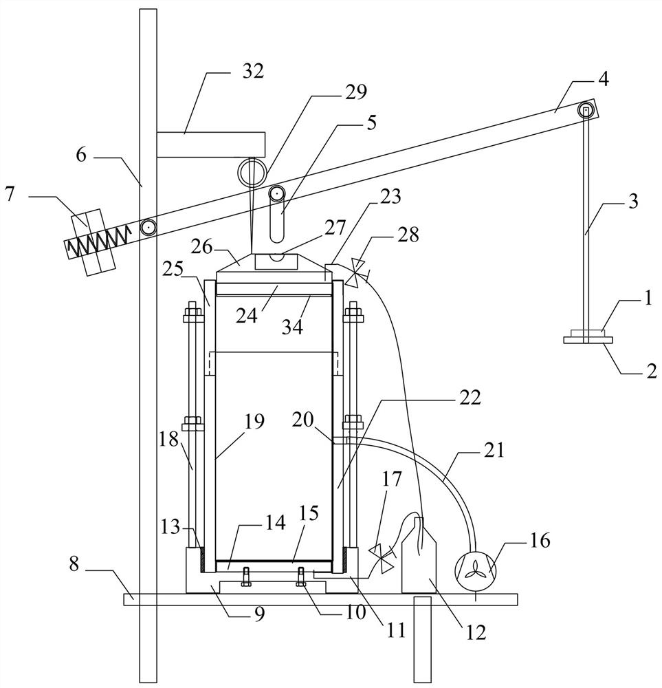
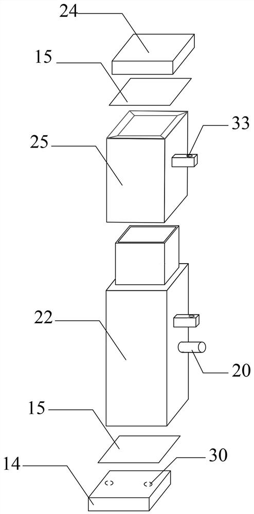
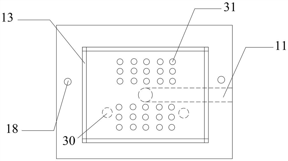
[0038] A sample preparation device for making samples for geotechnical true triaxial tests, such as Figure 1-5As shown, it includes a loading platform, a consolidation device and a loading device that applies pressure downward to the top of the consolidation device in the vertical direction. The loading platform is a flat plate 8 with legs. The knotting device comprises a drainage base 9 with a fixed groove, at least two screw rods 18 arranged on the groove wall of the drainage base, a cylindrical sample preparation frame 22 inserted in the fixed groove and open at both ends, arranged on the sample preparation frame Auxiliary frame 25 on the top, a cylindrical latex film 19 located in the sample preparation frame, a lower water-permeable plate 14 located at the inner bottom of the latex film, a first filter paper 15 located above the lower water-permeable plate, an upper filter paper 15 located in the auxiliary frame The permeable plate 24, the second filter paper 34 arranged...
Embodiment 2
[0042] Different from Example 1, as Figure 6 As shown, the upper end of the column 6 is provided with a crossbeam 32 and a displacement gauge 29 fixed on the crossbeam. The displacement gauge is located directly above the lever beam 4. The upper surface of the lever beam has a C-shaped slide with a cross section extending along the length direction of the lever beam. Not shown in the groove diagram, the detection part of the displacement meter is slidably engaged in the chute, and there is a scale 35 on the lever beam. When measuring the magnitude of soil settlement deformation, the distance from the detection part to the starting point, the distance from the loading rod to the starting point, and the downward movement distance of the displacement meter are known, and the vertical displacement of the bottom of the loading rod can be easily obtained through similar triangles, and then obtained The magnitude of soil settlement deformation.
Embodiment 3
[0044] The difference from the above-mentioned embodiment is that, if Figure 7 As shown, the sample preparation frame is a split structure, including two fastened C-shaped plates or two fastened L-shaped plates. This embodiment uses L-shaped plates 221, 222, and at least one pair of fastened contact surfaces There is a rubber sealing strip 223 on one side, and at least two sets of fastening lugs are arranged on both sides of each fastening seam from bottom to top, and each set of two fastening lugs 224, 225 facing each other is arranged through lug bolts. 226 and the corresponding sets of fastening ear plates 224, 225 fasten the two L-shaped plates together, and the rubber sealing strip prevents air leakage from the seam when pumping air. The sample preparation frame of this structure is convenient for real three After placing the sample on the axial test platform, remove the sample frame without damaging the sample.
[0045] In other embodiments, different from the above-me...
PUM
 Abstract
Description
Claims
Application Information
 - Generate Ideas
- Intellectual Property
- Life Sciences
- Materials
- Tech Scout
- Unparalleled Data Quality
- Higher Quality Content
- 60% Fewer Hallucinations
Browse by: Latest US Patents, China's latest patents, Technical Efficacy Thesaurus, Application Domain, Technology Topic, Popular Technical Reports.
© 2025 PatSnap. All rights reserved.Legal|Privacy policy|Modern Slavery Act Transparency Statement|Sitemap|About US| Contact US: help@patsnap.com


