Eureka AIR delivers breakthrough ideas for toughest innovation challenges, trusted by R&D personnel around the world.

A cabin-piercing adiabatic compression mechanism applied to an ultra-high vacuum cryogenic refrigeration system

A low-temperature refrigeration system and ultra-high vacuum technology, applied in household refrigeration devices, applications, household appliances, etc., can solve the problems of system vacuum damage, device temperature being difficult to maintain target low temperature, affecting the maintenance of ultra-high vacuum environment, etc., to avoid Damaged effect of compaction effect

Active Publication Date: 2022-06-24
西安应用光学研究所
View PDF0 Cites 0 Cited by
  • Summary
  • Abstract
  • Description
  • Claims
  • Application Information

AI Technical Summary

Problems solved by technology

[0002] In the ultra-high vacuum low-temperature refrigeration system, it is often necessary to compress and fix cryogenic devices of different shapes and sizes. Usually, a certain pressure must be given to the devices through the cabin compression mechanism, but the conventional vacuum cabin structure often has three aspects. Problems: First, factors such as additional leakage rate and material vacuum degassing caused by the penetration structure will damage the vacuum degree of the system to a certain extent, which will affect the maintenance of the ultra-high vacuum environment; The heat source is transmitted to the low-temperature device, which makes it difficult to maintain the target low temperature of the device; the third is that the penetrating mechanism will not be in close contact with the low-temperature device due to thermal expansion and contraction and vibration

Method used


Image

  • A cabin-piercing adiabatic compression mechanism applied to an ultra-high vacuum cryogenic refrigeration system

Examples


Embodiment Construction

[0018] In order to make the purpose, content and advantages of the present invention clearer, the specific embodiments of the present invention will be described in further detail below with reference to the accompanying drawings and embodiments.

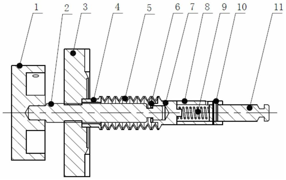
[0019] like figure 1 As shown in the figure, the cabin-penetrating adiabatic pressing mechanism of the present invention applied to an ultra-high vacuum and low-temperature refrigeration system includes an operating handwheel 1, a screw 2, a knife-edge flange 3, a bellows 5, a spring 9, and a thermal insulation column 11; the front part of the screw 2 Install the operating handwheel 1, the middle part is installed in the central threaded hole of the knife-edge flange 3 through threaded connection, the rear part is sleeved with a bellows 5, and the rear end of the screw 2 is connected to the rear joint II7 of the bellows 5; the front end of the bellows 5 is fixed On the knife-edge flange 3, the rear end is provided with a spring 9, a...


PUM


Abstract

The invention discloses a cabin-piercing adiabatic compression mechanism applied to an ultra-high vacuum low-temperature refrigeration system, which includes an operating handwheel, a screw, a knife-edge flange, a bellows, a spring, and a heat-insulating column; the front of the screw is equipped with an operating handwheel, The middle part is installed in the threaded hole in the center of the knife-edge flange through threaded connection, the rear part is sleeved with a bellows, and the rear end of the screw is connected to the rear joint II of the bellows; the front end of the bellows is fixed on the knife-edge flange, and the rear end is provided with a spring. A thermal insulation column movable along the axial direction is arranged at the rear end of the spring; turning the operating hand wheel drives the screw to move back and forth, and the bellows is compressed or extended. The present invention enables the operator to change the length of the screw extending into the vacuum chamber by rotating the handwheel to obtain different pressures for the heat insulation components, and to realize the compression of the low-temperature devices moving in the ultra-high vacuum chamber without causing excessive pressure in the chamber. The high-vacuum environment is destroyed; ceramic materials with low thermal conductivity are selected to make heat-insulating columns to achieve a certain heat-insulating effect.

Description

technical field [0001] The invention belongs to the technical field of ultra-high vacuum application, and relates to a cabin adiabatic pressing mechanism applied to an ultra-high vacuum low-temperature refrigeration system. Background technique [0002] In the ultra-high vacuum cryogenic refrigeration system, it is often necessary to press and fix low-temperature devices of different shapes and sizes, and it is usually necessary to apply a certain pressure to the devices through the penetration compression mechanism. However, the conventional vacuum penetration structure often has three aspects. Problems: First, the extra leak rate, material vacuum outgassing and other factors brought about by the piercing structure cause the system vacuum to be destroyed to a certain extent, which affects the maintenance of the ultra-high vacuum environment; The heat source is conducted to the low-temperature device, making it difficult for the device temperature to maintain the target low ...

Claims


Application Information

Patent Timeline
Patent Type & Authority Patents(China)
IPC IPC(8): F25D25/00F25D23/00
Inventor 俞兵袁林光秦艳范纪红杨传森卢耀文周青枝张灯
Owner 西安应用光学研究所
Why Eureka
Eureka Blog
Learn More