Al technical title is built by PatSnap Al team. It summarizes the technical point description of the patent document.
A technology for highway bridges and fences, applied in the directions of fences, roads, roads, etc., can solve the problems of easy toppling under the action of external force, bending deformation of L-shaped bending rods, deformation of construction fences, etc., so as to reduce maintenance workload and increase The difficulty of deformation and the effect of prolonging the service life
Active Publication Date: 2021-04-16
赵文庆
View PDF9 Cites 3 Cited by
Summary
Abstract
Description
Claims
Application Information
AI Technical Summary
This helps you quickly interpret patents by identifying the three key elements:
Problems solved by technology
Method used
Benefits of technology
Problems solved by technology
[0003] Existing fences used for highway and bridge construction are mainly composed of construction fences, load-bearing bases, L-shaped curved rods, plug-in pipes, etc., wherein the load-bearing bases are directly placed on the ground around the construction site, and the construction fences are fixedly installed on the load-bearing bases. The curved rod is installed on one side of the construction fence, and the plug-in pipe is fixedly installed on the other side of the construction fence. During installation, the two adjacent construction fences are flexibly connected together through the plug-in effect of the L-shaped curved rod and the plug-in pipe. However, the construction fence of this structure is less stable, and it is easy to fall under the action of external force, and the tipping of one construction fence will cause the adjacent construction fence to fall together, which will cause the construction fence to fall easily under the action of external force. A large amount of dumping caused the follow-up maintenance work to be more troublesome. At the same time, no energy-absorbing structure was installed, and the construction fence directly subjected to force was easily deformed under the action of external force. The service life is short, so it is urgent to design a fence for road and bridge construction
Method used
Image
Click on the blue label to locate the original text in one second.
Reading with bidirectional positioning of images and text.
Examples
Embodiment Construction
[0031] The technical solutions in the embodiments of the present invention will be clearly and completely described below in conjunction with the accompanying drawings in the embodiments of the present invention; obviously, the described embodiments are only some embodiments of the present invention; rather than all embodiments. Based on the embodiments of the present invention; all other embodiments obtained by persons of ordinary skill in the art without creative work; all belong to the protection scope of the present invention.
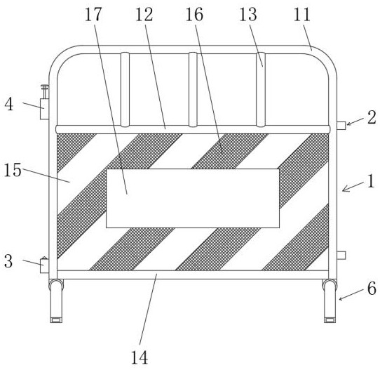
[0032] see Figure 1-9 , a fence used for highway bridge construction, comprising a construction fence 1, the right side of the construction fence 1 is provided with a socket device 2.
[0033] The construction fence 1 includes a U-shaped warning frame 11, the left side of the U-shaped warning frame 11 is provided with a lower locking device 3 and an upper locking device 4, the end of the U-shaped warning frame 11 is provided with a bearing device ...
PUM
Abstract
The invention discloses a highway bridge construction fence. The highway bridge construction fence comprises a construction fence body, and a socket device is arranged on the right side face of the construction fence body; the weight of a bearing device is increased through cooperation of a releasing device and a reinforcing device, the gravity center of the construction fence shifts downwards, and the stability is increased; the length of a force arm between the bearing device and the ground is increased through the reinforcing device, then the external force resistance of construction fence is improved, and the stability is better; through the cooperation of the socket device, a lower locking device, an upper locking device and a control device, the construction fence which are directly stressed can be automatically separated from the adjacent construction fences, it is ensured that the adjacent construction fences cannot be brought down by the construction fences which are directly stressed, and the subsequent maintenance work is simplified; and the external force borne by the construction fence is buffered and absorbed through the bearing device, the deformation difficulty of the construction fence under the external force is increased, and the service life of the construction fence is prolonged.
Description
technical field [0001] The invention relates to the field of road and bridge construction protection equipment, and more specifically relates to a fence used for road and bridge construction. Background technique [0002] Construction fence, also known as construction guardrail, is a finished iron pipe product, which is processed by layers of seamless iron pipe bending, welding, grinding and polishing, high-pressure baking paint, film sticking, etc. It is generally used on ordinary roads, expressways and There are highway crossroads at all levels, toll booths, bridges, parking lots, stations, docks, dangerous areas and road construction sites, temporary fences at assembly places and other places as road lanes, area enclosure safety isolation, diversion, guidance or used in It can also be used for the protection and protection of equipment and facilities in factories, workshops, warehouses, parking lots, commercial areas, public places, etc. To the role of isolation and warn...
Claims
Application Information
Patent Timeline
Application Date:The date an application was filed.
Publication Date:The date a patent or application was officially published.
First Publication Date:The earliest publication date of a patent with the same application number.
Issue Date:Publication date of the patent grant document.
PCT Entry Date:The Entry date of PCT National Phase.
Estimated Expiry Date:The statutory expiry date of a patent right according to the Patent Law, and it is the longest term of protection that the patent right can achieve without the termination of the patent right due to other reasons(Term extension factor has been taken into account ).
Invalid Date:Actual expiry date is based on effective date or publication date of legal transaction data of invalid patent.