Embroidery machine

An embroidery machine and machine head technology, which is applied in the field of embroidery machines, can solve the problems that the strength of the main shaft cannot meet the driving requirements of the embroidery machine, the size of the embroidery machine increases, and the size of the main shaft is limited, so as to improve maintenance efficiency, increase strength, The effect of reducing the difficulty of maintenance

Pending Publication Date: 2021-04-16
ZHEJIANG XINSHENG SEWING EQUIP
View PDF0 Cites 1 Cited by
  • Summary
  • Abstract
  • Description
  • Claims
  • Application Information

AI Technical Summary

Problems solved by technology

In the existing embroidery machine structure, due to the setting of the main shaft through the machine head, the size of the main shaft is limited, and the strength of the main shaft cannot well meet the driving requirements of the embroidery machine
If the strength of the main shaft is increased by increasing the outer diameter of the main shaft, in order to reserve enough installation space, the overall size of the machine head must also be increased accordingly, and the shape of the embroidery machine will also increase accordingly, which is not conducive to controlling production. cost
In addition, when the main shaft is deformed or broken and needs to be replaced, the needle bar driving mechanism and presser foot driving mechanism on all machine heads need to be separated from the main shaft, which makes maintenance more complicated.

Method used


Image

  • Embroidery machine
  • Embroidery machine
  • Embroidery machine

Examples


Embodiment 1

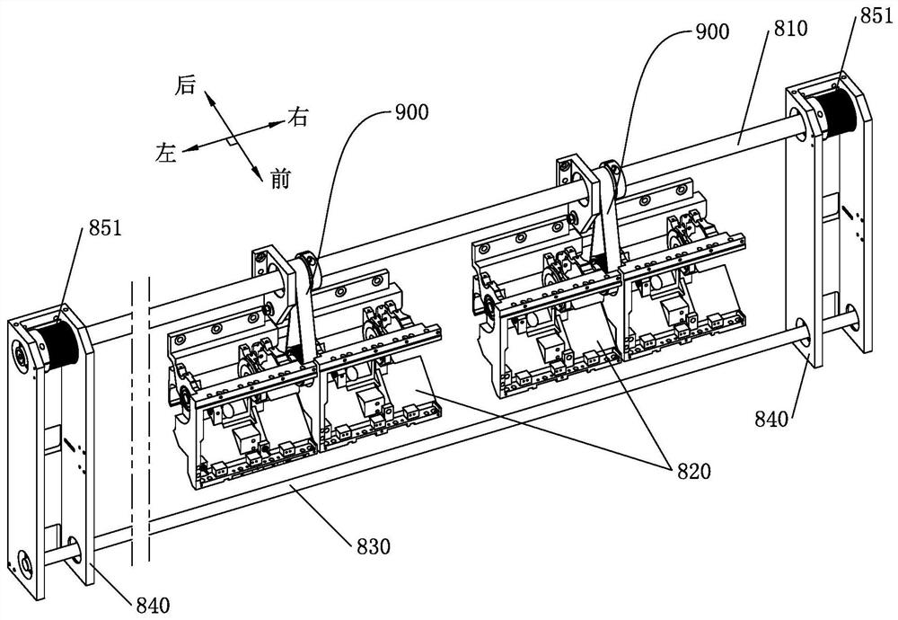
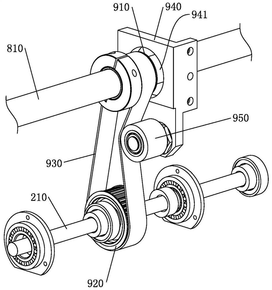
[0036] like Figure 1 to Figure 10 As shown, the present invention provides an embroidery machine, including a horizontal main shaft 810, a main drive motor for driving the main shaft 810, and a plurality of head modules 820 arranged at intervals along the lateral direction, and the main shaft 810 is arranged on each head module 820 Externally, each head module 820 includes at least one head. The machine head includes a casing 100, a needle bar driving shaft 210, a guide rod 310, a needle bar driver 320, a needle bar cam 220, a connecting rod structure 400, a presser foot structure 500, a presser foot driving wheel 240, and a presser foot transmission mechanism 600. The rod driving shaft 220 is rotatably placed horizontally on the casing 100. A split drive transmission mechanism 900 is provided between the needle rod driving shafts of each head module 820 and the main shaft 810. The guide rod 310 is vertically placed on the casing. The driver 320 is sleeved on the guide rod 3...


PUM


Abstract

The invention discloses an embroidery machine, and belongs to the technical field of embroidery equipment. The embroidery machine comprises an upper shaft, a main driving motor and a plurality of machine head modules, wherein a main shaft is arranged outside each machine head module, each machine head module comprises at least one machine head, the machine head comprises a machine shell, a needle rod driving shaft, a guide rod, a needle rod driver, a needle rod cam, a connecting rod structure, a presser foot structure, a presser foot driving wheel and a presser foot transmission mechanism, the connecting rod structure is arranged between the needle rod cam and the needle rod driver and used for driving the needle rod driver to move up and down, and the presser foot transmission mechanism is arranged between the presser foot driving wheel and the presser foot mechanism and used for driving the presser foot mechanism to move up and down. Due to the fact that the main shaft is arranged outside the machine head module, the strength of the main shaft can be improved by increasing the outer diameter of the main shaft, and thus the structural requirement of the embroidery machine is better met. When the main shaft needs to be replaced, only related components of a sub-drive transmission mechanism need to be detached from the main shaft, and components on the machine head module do not need to be detached.

Description

technical field [0001] The invention relates to the technical field of embroidery equipment, in particular to an embroidery machine. Background technique [0002] With the advancement of science and technology, computerized embroidery machines have now become the main mechanical equipment in the embroidery industry, and the head of the embroidery machine is an important structure of the embroidery machine. In the existing embroidery machine structure, a main shaft passes through all the machine heads to provide power for the needle bar drive and the presser foot drive on each machine head. With the improvement of market demand, the number of heads on the embroidery machine continues to increase, so the rigidity requirements for the main shaft are also getting higher and higher. In the existing embroidery machine structure, due to the setting of the main shaft passing through the machine head, the size of the main shaft is limited, and the strength of the main shaft cannot w...

Claims


Application Information

Patent Timeline
Patent Type & Authority Applications(China)
IPC IPC(8): D05C11/06D05C9/20
Inventor 王海江田桂郁
Owner ZHEJIANG XINSHENG SEWING EQUIP
Why Eureka
Try Eureka