
Mixing device for breeding

A mixing device and mixing technology, applied in the field of breeding, can solve the problems of insufficient mixing, affecting the service life of the motor, and insufficiently uniform growth of livestock, and achieve the effects of reducing the rotating force, increasing the uniformity, and fully mixing

Inactive Publication Date: 2021-04-16
五河县纬立农业科技有限公司
View PDF0 Cites 1 Cited by
  • Summary
  • Abstract
  • Description
  • Claims
  • Application Information

AI Technical Summary

Problems solved by technology

In order to ensure that the feed eaten by animals contains all the nutrients specified in the feeding standards, it is necessary to select and match the feed materials accordingly; in ordinary mixing devices, the feeding materials are not mixed uniformly, As a result, the growth of livestock is not uniform, and the ordinary mixing device has high requirements on the power of the motor, which affects the service life of the motor. Therefore, we propose a mixing device for breeding

Method used


Image

  • Mixing device for breeding
  • Mixing device for breeding
  • Mixing device for breeding

Examples


Embodiment 1

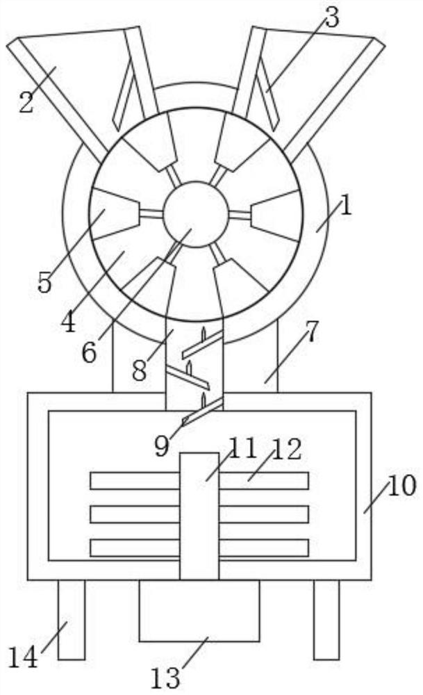
[0017] see Figure 1-2 , the present invention provides a technical solution: a mixing device for breeding, including a first mixing shell 1, the upper end of the first mixing shell 1 is fixedly connected with feeding chambers 2 on the left and right sides, and the mixing The ingredients are put into the feeding chamber 2, and the inner cavity of the feeding chamber 2 is fixedly connected with a baffle plate 3. In order to limit the amount of the material in the feeding chamber 2 entering the trapezoidal groove 5, the baffle plate 3 is 60° away from the horizontal plane. degree to 65 degrees, the surface of the baffle 3 is smooth. The inner cavity of the first mixing housing 1 is movably connected with a rotating roller 4, which also plays a certain mixing role in order to transfer the material in the feeding chamber 2, and the outer side of the rotating roller 4 is provided with a trapezoidal Groove 5, trapezoidal groove 5 In order to have the mixed material, the middle part...

Embodiment 2

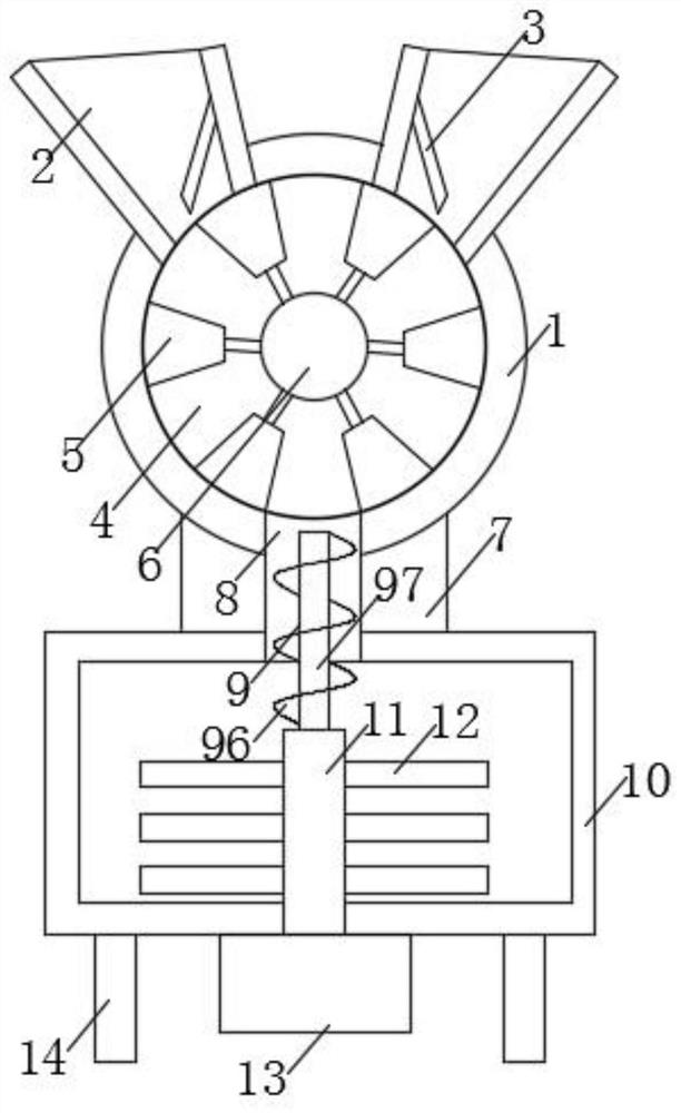
[0020] see image 3 The present invention provides a technical solution: a reduction shaft 97 is plugged into the middle of the inner cavity of the feeding chamber 8, the lower end of the reduction shaft 97 is fixedly connected to the upper end of the transmission rod 11, and the side wall of the reduction shaft 97 A deceleration impeller 96 is wrapped on the top, and the deceleration impeller 96 is helical.

[0021] Working principle: when the material enters the feeding chamber 8, the motor 13 drives the transmission rod 11 to rotate, so that the decelerating shaft 97 and the decelerating impeller 96 rotate, which can make the material falling from the feeding chamber 8 turn over and fall, making the mixing of materials more efficient. full.


PUM


Abstract

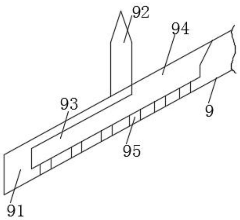
The invention discloses a mixing device for breeding. The mixing device comprises a first mixing shell, feeding cavities are fixedly connected to the left side and the right side of the upper end of the first mixing shell, baffles are fixedly connected to inner cavities of the feeding cavities, rotating rollers are movably connected to the inner cavities of the first mixing shell, and trapezoidal grooves are formed in the outer sides of the rotating rollers; a material mixing groove is formed in the middle of each rotating roller, the lower end of the first material mixing shell is connected with a second material mixing shell through a connecting column, a feeding cavity is formed in the middle of the connecting column, a speed reducing mechanism is fixedly connected to the interior of the feeding cavity, and the speed reducing mechanism comprises a speed reducing plate, a partition plate, a speed reducing cavity, a feeding port, a discharging hole, a speed reducing impeller and a speed reducing shaft. According to the mixing device for breeding, through the arrangement of the structure of the speed reducing plate, falling materials are fully mixed; and through the arrangement of the structure of the speed reducing shaft and the speed reducing impeller, the materials are mixed more fully.

Description

technical field [0001] The invention relates to the technical field of breeding, in particular to a mixing device for breeding. Background technique [0002] Breeding includes livestock farming, poultry farming, aquaculture, and special farming. The feeding standards stipulate the requirements of animals for various nutrients under certain conditions. Its expression is either expressed by the quantity of various nutrients that each animal needs to supply per day, or expressed by the concentration of various nutrients in unit weight. It is an important technical parameter to match the balanced diet of livestock and poultry and scientifically raise livestock and poultry. Listed in the feed composition table is the content of various nutrients in different types of feed raw materials. In order to ensure that the feed eaten by animals contains all the nutrients specified in the feeding standards, it is necessary to select and match the feed materials accordingly; in ordinary m...

Claims


Application Information

Patent Timeline
IPC IPC(8): B01F13/10B01F7/18B01F7/24B01F5/24A23N17/00
Inventor 顾春雨
Owner 五河县纬立农业科技有限公司
Learn More