Wood board perforating device for civil construction
A punching device and a technology for civil engineering, applied in fixed drilling machines and other directions, can solve the problems of time-consuming, difficulty in ensuring punching accuracy, and inconvenience.
- Summary
- Abstract
- Description
- Claims
- Application Information
AI Technical Summary
Problems solved by technology
Method used
Image


Examples
Embodiment 1
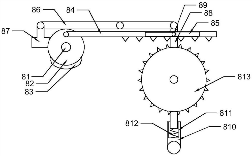
[0033] Such as Figure 2 to Figure 4 As shown, in the embodiment of the present invention, the intermittent rotating device 8 includes a rotating motor 81, a turntable 82 is fixedly installed on the turntable 81, a bump 83 is installed on one side of the turntable 82, and A gear bar 84 is hinged eccentrically, and a chute 85 is opened on the gear bar 84; a rotary rod 86 is hinged on the side wall of the cabinet 3, and a weight block 87 is hinged on the side wall of the rotary rod 86 close to the turntable 82, so that The other end of the rotating rod 86 is hinged with a control rod 88, and a slide block 89 is installed on the control rod 88, and the slide block 89 is located inside the chute 85; the bottom of the cabinet 3 is hinged with a rotating rod 810, and the rotating rod The other end of 810 has a groove 811, and a spring 812 is installed at the bottom of the groove 811, and the other end of the spring 812 is fixedly connected with the control rod 88; The rod 84 cooper...
Embodiment 2
[0037] Such as Figure 5 to Figure 12 As shown, in the embodiment of the present invention, the reciprocating punching device 9 includes a first connecting column 91, the first connecting column 91 is fixedly installed on the inner wall of the top of the control box 12, and one end of the first connecting column 91 is fixed A second motor 92 is installed, and a rotating rod 93 is installed inside the second motor 92, and a first rotating disc 94 and a second rotating disc 95 are respectively fixedly installed at both ends of the rotating rod 93, and the first rotating disc 94 A diamond-shaped groove 96 is opened on the top, and a fan-shaped groove 97 is opened on the second rotating disk 95; a plate groove 98 is opened on the bottom of the control box 12, and a first sliding plate 910 and a second sliding plate 910 are arranged inside the plate groove 98. plate 911, the first sliding plate 910 and the second sliding plate 911 are fixedly connected, the first sliding plate 910 ...
Embodiment 3
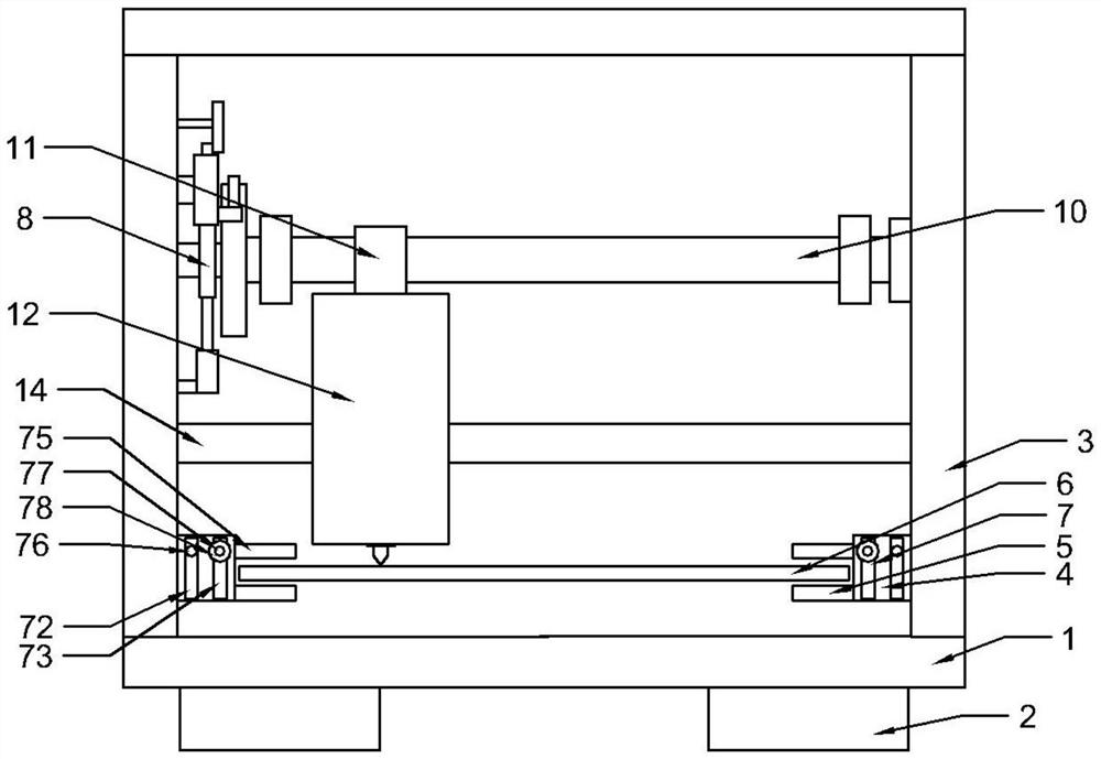
[0044] Such as Figure 1 to Figure 13 As shown, in the embodiment of the present invention, the fixing device 7 includes a fixing groove 71, the fixing groove 71 is opened on the side of the connecting platform 4, and the side wall of the fixing groove 71 has a first through groove 72 and a second through groove. Through groove 73, described fixing groove 71 inside is provided with positioning bar 74, and described positioning bar 74 one end is equipped with fixing plate 75, and described positioning bar 74 is equipped with first fixing bar 76 and second fixing bar 77, described The first fixed rod 76 and the second fixed rod 77 are located inside the first through groove 72 and the second through groove 73 respectively, the side walls of the second fixed rod 77 are provided with threads, and the second fixed rod 77 is sleeved with Nut 78 is provided.
[0045] During use, the plank 6 is placed on the support plate 5, then slide the fixing plate 75 downwards so that the fixing...
PUM
 Abstract
Description
Claims
Application Information
 - R&D
- Intellectual Property
- Life Sciences
- Materials
- Tech Scout
- Unparalleled Data Quality
- Higher Quality Content
- 60% Fewer Hallucinations
Browse by: Latest US Patents, China's latest patents, Technical Efficacy Thesaurus, Application Domain, Technology Topic, Popular Technical Reports.
© 2025 PatSnap. All rights reserved.Legal|Privacy policy|Modern Slavery Act Transparency Statement|Sitemap|About US| Contact US: help@patsnap.com