Light beam switching mechanism of laser engraving and cutting machine
A technology of laser engraving and switching mechanism, used in laser welding equipment, welding equipment, metal processing equipment and other directions, can solve problems such as inability to cope
- Summary
- Abstract
- Description
- Claims
- Application Information
AI Technical Summary
Problems solved by technology
Method used
Image
Examples
Embodiment 1
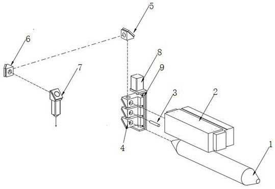
[0027] Such as figure 1 As shown, the first mirror frame 4 moves vertically: the vertical movement mechanism includes a first screw motor 8 and a first longitudinal linear guide 9, and the first longitudinal linear guide 9 is provided with the first mirror frame 4, The first screw motor 8 correspondingly drives the first reflector frame 4 to move longitudinally on the first longitudinal linear guide rail 9 and is arranged horizontally with the vertically arranged high-performance laser 2, red light diode 3 and high-power laser 1. corresponding to each end.
Embodiment 2
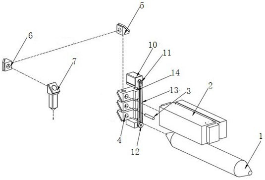
[0029] Such as figure 2 As shown, the first mirror frame 4 moves vertically: the vertical movement mechanism includes a first optical axis motor 10, a first driving wheel 11, a first driven wheel 12, a first synchronous belt 13 and a second longitudinal linear guide rail 14, The first optical axis motor 10 corresponds to drive the first driving wheel 11, the first synchronous belt 13 is arranged on the first driving wheel 11 and the first driven wheel 12, and the second longitudinal linear guide rail 14 is synchronous with the first The belts 13 are arranged in parallel, the first mirror frame 4 is correspondingly arranged on the second longitudinal linear guide rail 14 and is driven to move longitudinally by the first synchronous belt 13, and the first optical axis motor 10 is correspondingly driven to drive the first mirror frame 4 It moves on the second longitudinal linear guide rail 14 and corresponds to the high-performance laser 2 , the red light diode 3 and the emittin...
Embodiment 3
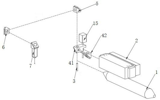
[0033] Such as image 3As shown, the first mirror frame 4 rotates and moves: the rotary movement mechanism includes a second optical axis motor 15, the second optical axis motor 15 is arranged vertically and the driving end is set downward, and the first mirror frame 4 Including a first rotating mirror frame 41 and a second rotating mirror frame 42, the first rotating mirror frame 41 and the second rotating mirror frame 42 are arranged at the driving end of the second optical axis motor 15 in an up-and-down dislocation, the The second mirror frame 5 corresponds up and down with the first rotating mirror frame 41 and the second rotating mirror frame 42 respectively. Correspondingly, the high-power laser 1 is arranged horizontally and the emitting end corresponds to the second mirror frame 5 through the second rotating mirror frame 42 , and the red light diode 3 is arranged vertically and the emitting end is arranged to correspond to the second mirror frame 5 .
[0034] The con...
PUM
 Abstract
Description
Claims
Application Information
 - R&D
- Intellectual Property
- Life Sciences
- Materials
- Tech Scout
- Unparalleled Data Quality
- Higher Quality Content
- 60% Fewer Hallucinations
Browse by: Latest US Patents, China's latest patents, Technical Efficacy Thesaurus, Application Domain, Technology Topic, Popular Technical Reports.
© 2025 PatSnap. All rights reserved.Legal|Privacy policy|Modern Slavery Act Transparency Statement|Sitemap|About US| Contact US: help@patsnap.com


