
Improved split type ejector rod structure of hot forging die

A hot forging die, split-type technology, applied in the direction of manufacturing tools, forging/pressing/hammer devices, forging/pressing/hammering machinery, etc., can solve the problems of ejector rod breakage, inconvenient ejector rod disassembly and installation, etc., to reduce Bearing force, easy to install and disassemble the ejector rod, and solve the effect of easy breakage

Pending Publication Date: 2021-04-13
太仓市海丰金属制品有限公司
View PDF0 Cites 0 Cited by
  • Summary
  • Abstract
  • Description
  • Claims
  • Application Information

AI Technical Summary

Problems solved by technology

[0004] In order to solve the above problems, the object of the present invention is to provide an improved hot forging die split ejector structure, to solve the above-mentioned background technology that is inconvenient for the staff to disassemble and install the ejector and the gap between the ejector and the grinding tool. Stamping can easily lead to the problem that the ejector pin breaks

Method used

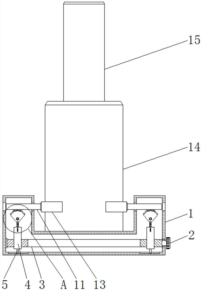
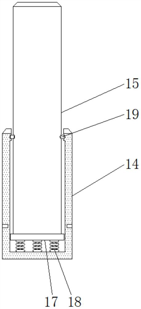
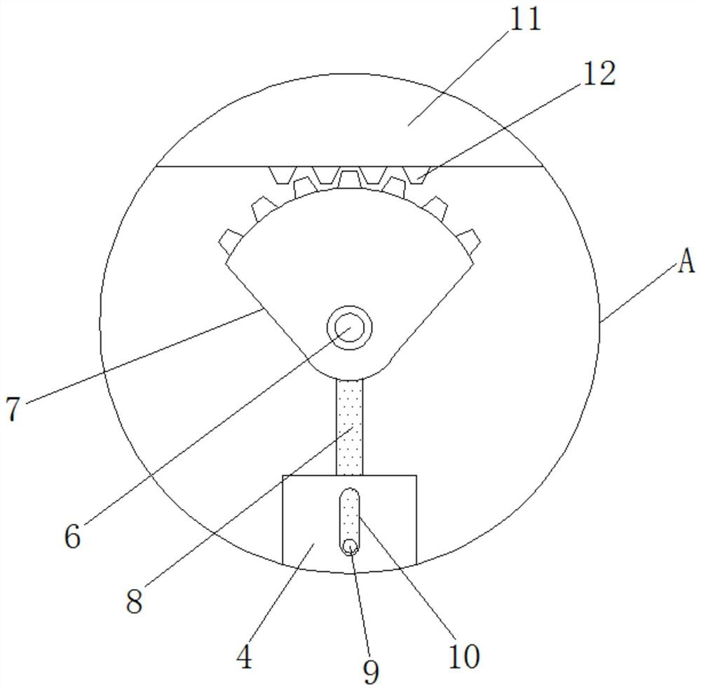

Image

  • Improved split type ejector rod structure of hot forging die
  • Improved split type ejector rod structure of hot forging die
  • Improved split type ejector rod structure of hot forging die

Examples


Embodiment Construction

[0017] In order to explain the overall concept of the present invention more clearly, the following will be described in detail by way of examples in conjunction with the accompanying drawings.

[0018] In describing the present invention, it is to be understood that the terms "center", "upper", "lower", "front", "rear", "left", "right", "vertical", "horizontal", The orientation or positional relationship indicated by "top", "bottom", "inner", "outer", "axial", "radial" and "circumferential" are based on the orientation or positional relationship shown in the drawings, only It is for the convenience of describing the present invention and simplifying the description, but does not indicate or imply that the referred device or element must have a specific orientation, be constructed and operated in a specific orientation, and thus should not be construed as limiting the present invention.

[0019] In addition, the terms "first" and "second" are used for descriptive purposes only...


PUM


Abstract

The invention discloses an improved split type ejector rod structure of a hot forging die. The improved split type ejector rod structure of the hot forging die comprises a mounting base, a rotary knob is rotatably connected to the outer wall of the mounting base, one end of the rotary knob penetrates through the inner wall of the mounting base to be connected with a lead screw, a movable plate is rotatably connected to the outer wall of the lead screw, and a limiting block is fixed to the position, located on the inner wall of the mounting base, of the bottom of the movable plate; and a fixed shaft is fixedly arranged on the inner wall of the mounting base, the outer wall of the fixed shaft is sleeved with a half gear, a connecting rod is fixed to the bottom of the half gear and located on the outer wall of the movable plate, and a guide column penetrating through the outer wall of the movable plate is fixed to the outer wall of the connecting rod. According to the improved split type ejector rod structure of the hot forging die, the lead screw, the guide column, a guide groove, the half gear and other parts are used in cooperation, the effect that an ejector rod is convenient to mount and dismount is achieved, and the problems that an existing split type ejector rod structure of the hot forging die is single, and dismounting and mounting by workers are inconvenient are solved.

Description

technical field [0001] The invention belongs to the technical field of ejector rods of hot forging dies, and in particular relates to an improved split ejector rod structure of hot forging dies. Background technique [0002] Forgings such as crankshafts and connecting rods are often produced by hot die forging with a press. After the middle forming, the ejector pushes the forging billet out of the mold cavity. With the continuous use of the split ejector of the hot forging die, the following problems have been found in the actual use process. The existing split ejector of the hot forging die The structure and installation structure is single, which is inconvenient for the staff to disassemble and install the ejector rod, and when the split ejector rod is used, the punching between the ejector rod and the abrasive tool can easily cause the ejector rod to bend and break. [0003] It should be noted that the above content belongs to the scope of the inventor's technical cognit...

Claims


Application Information

Patent Timeline
IPC IPC(8): B21J13/03B21J13/14
CPCB21J13/03B21J13/14
Inventor 沈建刚王煜孙蕴萍
Owner 太仓市海丰金属制品有限公司
Learn More