Eureka AIR delivers breakthrough ideas for toughest innovation challenges, trusted by R&D personnel around the world.

Punching equipment for high-end equipment manufacturing

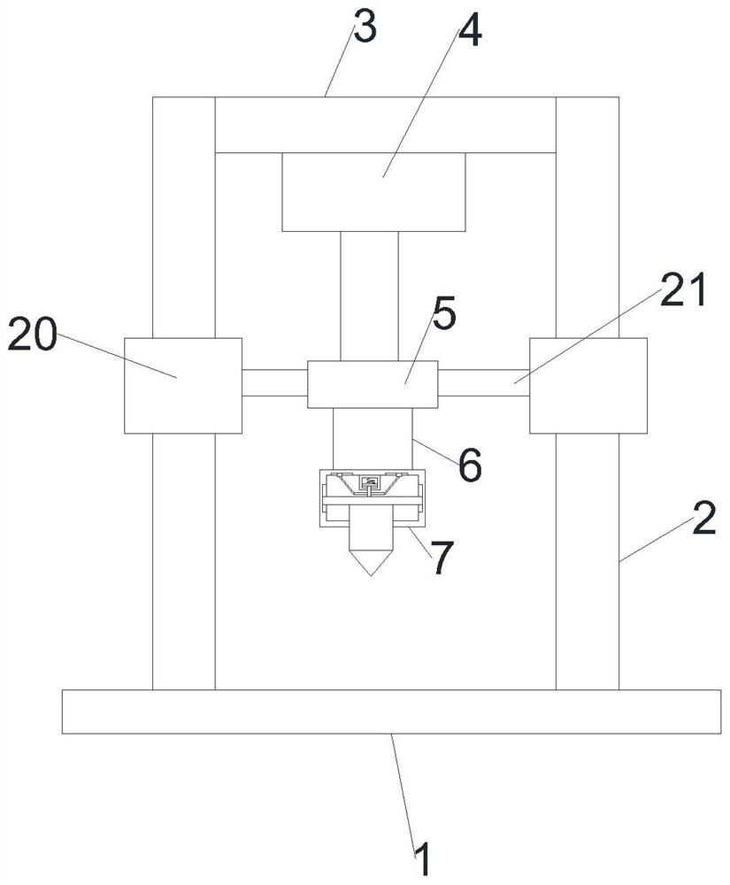
An equipment and punching technology, applied in the field of shooting training, can solve the problems of punch damage, maintenance, replacement, affecting punching efficiency, etc., to improve the life, protect the punch drill, and achieve the effect of stable fixation

Inactive Publication Date: 2021-04-13
合肥柔翰信息科技有限责任公司
View PDF0 Cites 0 Cited by
  • Summary
  • Abstract
  • Description
  • Claims
  • Application Information

AI Technical Summary

Problems solved by technology

[0003] When the existing punching equipment is punching, the punch will cause damage due to excessive punching force. At the same time, maintenance and replacement will not change, which will affect the efficiency of punching.

Method used


Image

  • Punching equipment for high-end equipment manufacturing
  • Punching equipment for high-end equipment manufacturing
  • Punching equipment for high-end equipment manufacturing

Examples


Embodiment Construction

[0028] The following will clearly and completely describe the technical solutions in the embodiments of the present invention with reference to the accompanying drawings in the embodiments of the present invention. Obviously, the described embodiments are only some, not all, embodiments of the present invention. Based on the embodiments of the present invention, all other embodiments obtained by persons of ordinary skill in the art without making creative efforts belong to the protection scope of the present invention.

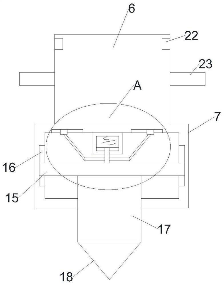
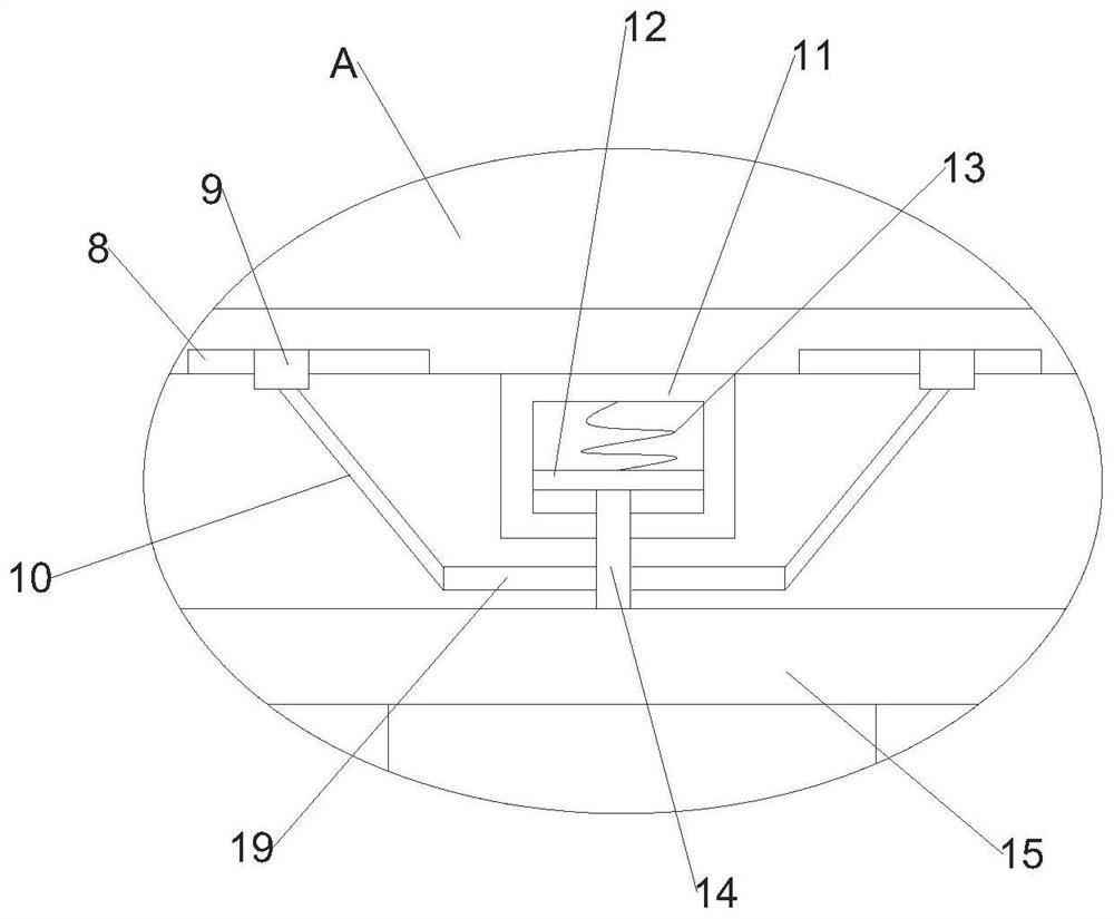
[0029] see Figure 1-6 , in an embodiment of the present invention, a high-end equipment manufacturing punching equipment, including a base 1, the upper part of the base 1 is symmetrically provided with a fixed column 2, and the top of the two fixed columns 2 is jointly fixed with a top seat 3, and the top seat 3 is provided with There is a cylinder 4, the free end of the cylinder 4 is connected with an installation mechanism 5, the bottom of the installation ...


PUM


Abstract

The invention discloses punching equipment for high-end equipment manufacturing. The punching equipment comprises a base, wherein fixing columns are symmetrically arranged on the upper portion of the base, a top seat is jointly fixed to the top ends of the two fixing columns, an air cylinder is arranged on the top seat, the free end of the air cylinder is connected with an installing mechanism, a detaching column is detachably arranged at the bottom of the installing mechanism, an anti-impact box is fixedly arranged at the bottom end of the detaching column, anti-impact grooves are symmetrically formed in the inner top wall of the anti-impact box, anti-impact blocks are slidably arranged inside the anti-impact grooves, anti-impact inclined rods are hinged to the anti-impact blocks, and an anti-impact sleeve box is arranged between the two anti-impact grooves. According to the punching equipment, during punching, a punch drill moves downwards to drive a punch column to buffer upwards, then an impact plate stably slides upwards inside a stabilizing groove, an impact column moves upwards to drive a sliding block to slide inside the anti-impact sleeve box and an anti-impact spring to compress, and meanwhile, an auxiliary column drives the anti-impact inclined rods to move, and then the anti-impact blocks slide inside the anti-impact grooves, so that the buffering effect is achieved, and the punch drill is protected.

Description

technical field [0001] The invention relates to the technical field of shooting training, in particular to a high-end equipment manufacturing punching equipment. Background technique [0002] The high-end equipment manufacturing industry refers to the high-end field of the equipment manufacturing industry. "High-end" is mainly manifested in three aspects: first, high-tech content, manifested as intensive knowledge and technology, reflecting the inheritance of multi-disciplinary and multi-field high-precision technology; Second, it is at the high end of the value chain and has the characteristics of high added value; third, it occupies a core position in the industrial chain, and its development level determines the overall competitiveness of the industrial chain. In the process of high-end equipment manufacturing and processing, it is often necessary to punch the equipment. [0003] When the existing punching equipment is punching, the punch will cause damage due to excessi...

Claims


Application Information

Patent Timeline
Patent Type & Authority Applications(China)
IPC IPC(8): B21D28/34B21D37/04
CPCB21D28/34B21D37/04
Inventor 马腾飞
Owner 合肥柔翰信息科技有限责任公司
Why Eureka
Eureka Blog
Learn More