Topping depth testing device and method

A technology of in-depth testing and top adjustment, applied in the field of optical communication, can solve cumbersome problems, achieve the effect of ensuring accuracy and reliability, improving measurement efficiency, and simplifying the testing process

Inactive Publication Date: 2021-04-09
武汉永鼎光通科技有限公司
View PDF5 Cites 2 Cited by
  • Summary
  • Abstract
  • Description
  • Claims
  • Application Information

AI Technical Summary

Problems solved by technology

[0003] In view of this, the embodiment of the present invention provides a roof adjustment depth testing device and method to solve the problem that the existing roof adjustment depth testing methods are relatively cumbersome

Method used


Image

  • Topping depth testing device and method
  • Topping depth testing device and method

Examples


Embodiment Construction

[0020] In order to make the purpose, features and advantages of the present invention more obvious and understandable, the technical solutions in the embodiments of the present invention will be clearly and completely described below in conjunction with the accompanying drawings in the embodiments of the present invention. Obviously, the following The described embodiments are only some, not all, embodiments of the present invention. Based on the embodiments of the present invention, all other embodiments obtained by persons of ordinary skill in the art without creative work belong to the protection scope of the present invention. The principles and features of the present invention will be described below in conjunction with the accompanying drawings. The examples given are only used to explain the present invention, not to limit the scope of the present invention.

[0021] The term "comprising" and other expressions with similar meanings in the description or claims of the p...


PUM


Abstract

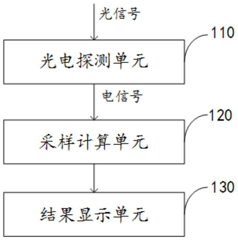
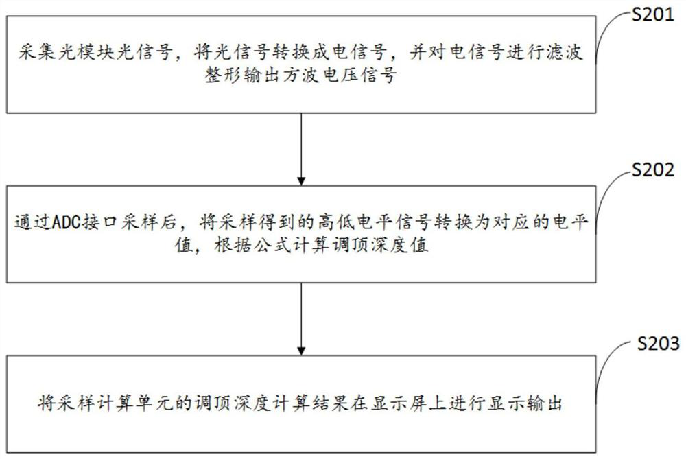
The invention provides a topping depth testing device and method. The device comprises a photoelectric detection unit which is used for converting an optical signal into an electric signal, carrying out the filtering and shaping of the electric signal, and outputting a square-wave voltage signal; A sampling calculation unit is used for converting the sampled high-low level signals into corresponding level values after sampling through an ADC interface, and the MCU is used for calculating a topping depth value according to a formula; A result display module is used for displaying and outputting the topping depth calculation result of the sampling calculation unit on a display screen. According to the scheme, the topping depth testing process of the optical module can be simplified, and the accuracy and reliability of a measurement result are guaranteed.

Description

technical field [0001] The invention relates to the field of optical communication, in particular to a device and method for testing the depth of top adjustment. Background technique [0002] From the second half of 2019, China Mobile began to promote the use of MWDM optical modules with top adjustment function in the field of 5G fronthaul, and released a series of application enterprise and industry standards. Among them, for the amplitude modulation module, the specification definition of top adjustment depth 3% to 5%. At present, the test method for the depth of the top adjustment has been relatively cumbersome, and there are two commonly used methods: one is to test with an optical probe and an oscilloscope, and then perform manual calculation; the other is to fly the line from the receiving RSS I pin of the module , Test the high and low levels with an oscilloscope, and then perform manual calculations. However, the testing process of the top adjustment depth in these...

Claims


Application Information

Patent Timeline
Patent Type & Authority Applications(China)
IPC IPC(8): H04B10/07
CPCH04B10/07
Inventor 高南京周志勇石旨博
Owner 武汉永鼎光通科技有限公司
Why Eureka
Try Eureka