
Wire peeling device based on power system cable construction, and construction method thereof

A peeling device and power system technology, applied in cable installation, cable installation device, equipment for dismantling/armoring cables, etc. Guaranteed quality and service life, novel design, easy to carry

Pending Publication Date: 2021-04-09
国网河南省电力公司新郑市供电公司 +1
View PDF0 Cites 2 Cited by
  • Summary
  • Abstract
  • Description
  • Claims
  • Application Information

AI Technical Summary

Problems solved by technology

[0002] In the cable laying construction of the cable switch cabinet, it is often necessary to lay and connect the cables. Generally, the cables are first laid into the switch cabinet, and then the cable head is peeled and then the joint operation is performed; since one end of the cable has been fixed to the switch cabinet However, the length of the cable terminal is limited, and the general staff uses pliers to peel the cable bit by bit from the cable terminal until all the required wiring parts are exposed; while there are many cables in the switch cabinet, it takes time to peel them with pliers Laborious; and for the larger cable stripping device, it is not easy to carry, and due to the length and position of the cable terminal, and one end has been fixed in the switch cabinet, it is impossible to quickly strip the cable

Method used


Image

  • Wire peeling device based on power system cable construction, and construction method thereof
  • Wire peeling device based on power system cable construction, and construction method thereof
  • Wire peeling device based on power system cable construction, and construction method thereof

Examples


Embodiment Construction

[0041] Below in conjunction with accompanying drawing, the present invention will be further explained and illustrated:

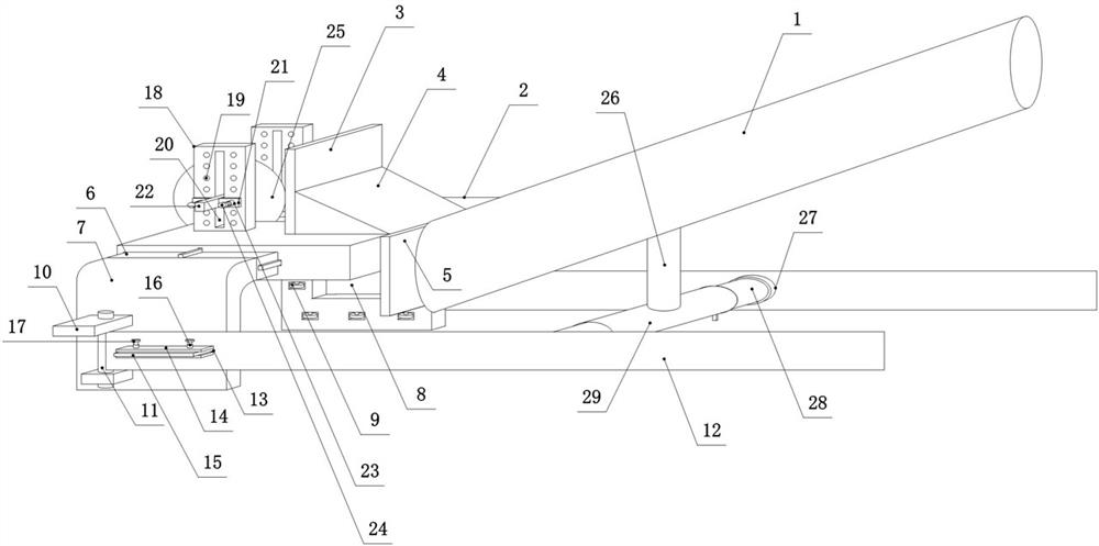
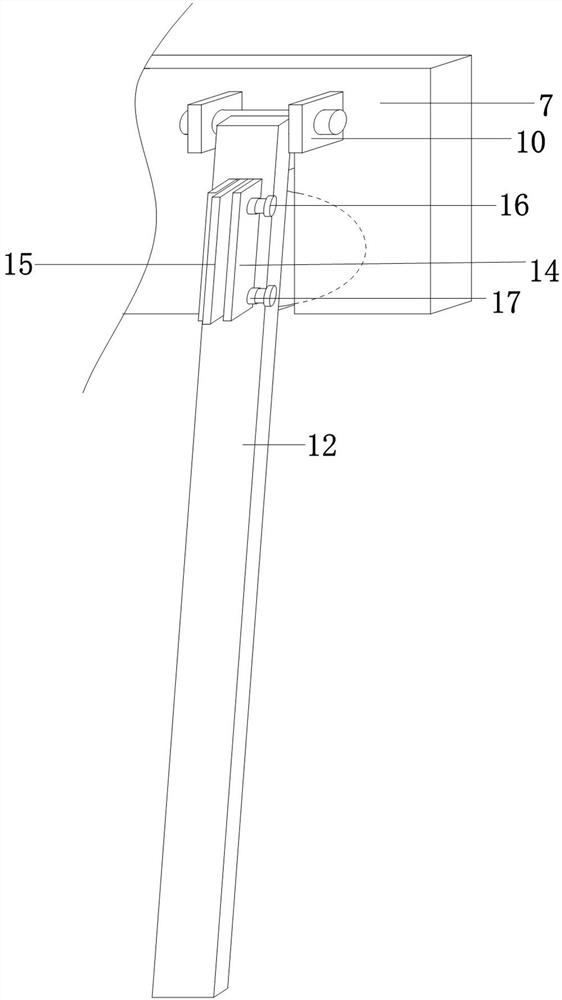
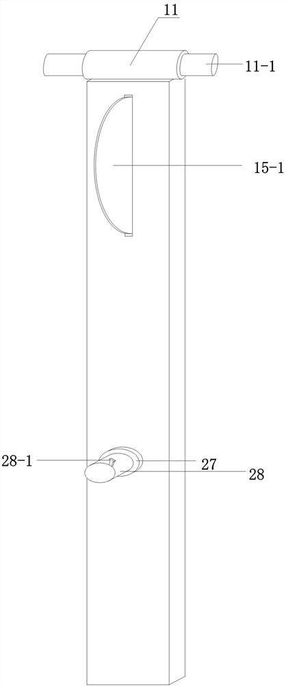
[0042] see Figure 1-Figure 7, a wire peeling device based on power system cable construction, including a handle 1, a top support plate 2, an insert plate 6 and a side pressure plate 12, the rear end of the top support plate 2 is fixed to the front end of the handle 1 by connecting the vertical plate 5 Connected together, a second "U"-shaped through hole 2-1 is dug in the middle of the top support plate 2, and second baffles 18 are respectively arranged on both sides of the second "U"-shaped through-hole 2-1 A circular blade 25 is slidably connected between the two second baffles 18 through a connecting rod 22, and the bottom of the circular blade 25 is facing the middle position of the second "U"-shaped through hole 2-1; supported on the top Grooves 22 are respectively dug on both sides of the board 2, and insert boards 6 are respectively inserted in eac...


PUM


Abstract

The invention discloses a wire peeling device based on power system cable construction, and a construction method thereof. The device comprises a handle, a top supporting plate, inserting plates, and a side pressing plate, the rear end of the top supporting plate is fixedly connected with the front end of the handle through a connecting vertical plate, and a second U-shaped through hole is dug in the middle of the top supporting plate. Second baffles are arranged on the two sides of the second U-shaped through hole respectively, a circular blade is connected between the two second baffles in a sliding mode through a connecting rod, grooves are dug in the two sides of the top supporting plate respectively, and the inserting plates are inserted into the grooves. A bent plate is arranged at the end portion of each inserting plate, and a cutting assembly is arranged on the bent plate. The device is suitable for cables with different diameters, the distance between the blades can be adjusted according to the thickness of the cable sheath, the cable and the sheath can be quickly separated, the situation that the blades penetrate into the cable sheath too deep and damage a cable core can be avoided, and the device is practical, convenient to use, easy to operate, time-saving, labor-saving, convenient to carry and easy to popularize.

Description

Technical field: [0001] The invention relates to a portable guide peeling device and a specific peeling construction method, in particular to a wire peeling device and a construction method based on power system cable construction. Background technique: [0002] In the cable laying construction of the cable switch cabinet, it is often necessary to lay and connect the cables. Generally, the cables are first laid into the switch cabinet, and then the cable head is peeled and then the joint operation is performed; since one end of the cable has been fixed to the switch cabinet However, the length of the cable terminal is limited, and the general staff uses pliers to peel the cable bit by bit from the cable terminal until all the required wiring parts are exposed; while there are many cables in the switch cabinet, it takes time to peel them with pliers It is laborious; and for the larger cable stripping device, it is not easy to carry, and due to the length and position of the c...

Claims


Application Information

Patent Timeline
Patent Type & Authority Applications(China)
IPC IPC(8): H02G1/12H01R43/28
CPCH01R43/28H02G1/1219
Inventor 刘晓峰王彦超李宏升岳广记平志凯
Owner 国网河南省电力公司新郑市供电公司
Learn More