Kitchen garbage continuous classification device

A sorting device and kitchen waste technology, applied in the direction of garbage drying, filtration separation, separation methods, etc., can solve the problems of bacteria breeding, low efficiency of solid-liquid separation, health hazards, etc., achieve good results, eliminate the breeding of bacteria, and return materials convenient effect

Pending Publication Date: 2021-04-09
杭州郎稳智能科技有限公司
View PDF3 Cites 0 Cited by
  • Summary
  • Abstract
  • Description
  • Claims
  • Application Information

AI Technical Summary

Problems solved by technology

[0002] With the improvement of human living standards, the amount of domestic waste generated in human daily life is increasing day by day, especially kitchen waste. If it is not placed properly or not classified, it is easy to breed bacteria, causing serious environmental problems, and causing serious environmental problems. health hazard
[0003] However, the traditional solid-liquid separation device needs to completely unload the squeezed solid waste before feeding, otherwise the new material will impregnate the dried solid waste again, which leads to the low efficiency of solid-liquid separation and is easy to Provides more time for bacteria to grow

Method used


Image

  • Kitchen garbage continuous classification device
  • Kitchen garbage continuous classification device
  • Kitchen garbage continuous classification device

Examples


Embodiment 1

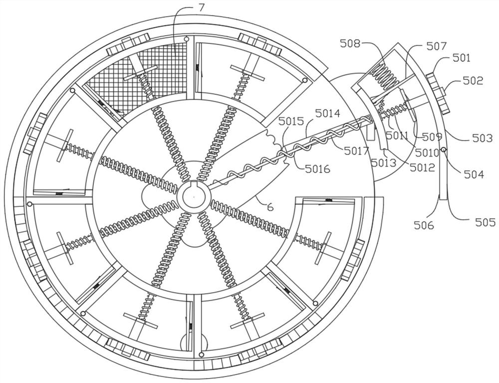
[0033] A continuous classification device for kitchen waste, including a housing, a base 4 and several separation devices 5 for solid-liquid separation, the separation devices 5 are rotatably arranged in the housing, and all the separation devices 5 are evenly distributed at equal angles Around the axis of the housing, a pusher compression device is arranged inside the separating device 5, and a plurality of ratchet devices 8 for cooperating with the pusher compression device are arranged inside the housing.

Embodiment 2

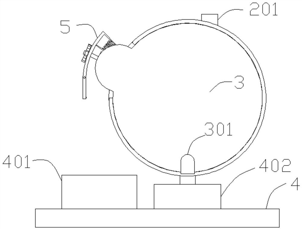
[0035] In a preferred embodiment of the present invention, on the basis of Embodiment 1, the housing includes a front shell 2, a sealing material shell 1 and a rear shell 3, and a rotating shaft 202 is provided through the middle of the front shell 2, so A feed pipe 201 is provided at the upper position of the front end surface of the front shell 2, and a support column 403 for supporting the shell is provided at the lower position of the front end surface of the front shell 2, and one end of the support column 403 is connected to the front shell. 2 is fixedly connected, the other end of the support column 403 is fixedly connected to the base 4, the sealing material shell 1 is arranged in the middle position between the front shell 2 and the rear shell 3, and the inner edge of the sealing material shell 1 There are several tooth pitches 9 arranged in a ring shape, and the tooth pitches 9 of several sections are composed of several tooth blocks. A separating cam 6 is fixedly arr...

Embodiment 3

[0037] In a preferred embodiment of the present invention, on the basis of Embodiment 1, the base 4 is provided with a water receiving bin 402 for receiving the waste water separated by the separation device, and the base 4 is provided with a water receiving bin 402 for receiving the waste water separated by the separation device. A receiving bin 401 for waste materials separated by the separation device 5 .


PUM


Abstract

The invention discloses a kitchen garbage continuous classification device, and belongs to the field of garbage classification. The kitchen garbage continuous classification device comprises a shell, a base and a plurality of separation devices for solid-liquid separation. The separation devices are rotatably arranged in the shell, and all the separation devices are uniformly distributed around the axis of the shell at equal angles. Material pushing compression devices are arranged in the separation devices, and a plurality of ratchet devices used for being matched with the material pushing compression devices are arranged in the shell. Kitchen waste can be continuously separated in a full-automatic mode, the labor cost is reduced, the solid-liquid separation effect is good, the efficiency is high, material returning is convenient, bacterium breeding is eradicated, and the kitchen garbage continuous classification device has safety and operability.

Description

technical field [0001] The invention relates to the field of waste sorting, in particular to a continuous kitchen waste sorting device. Background technique [0002] With the improvement of human living standards, the amount of domestic waste generated in human daily life is increasing day by day, especially kitchen waste. If it is not placed properly or not classified, it is easy to breed bacteria, causing serious environmental problems, and causing serious environmental problems. health hazard. [0003] However, the traditional solid-liquid separation device needs to completely unload the squeezed solid waste before feeding, otherwise the new material will impregnate the dried solid waste again, which leads to the low efficiency of solid-liquid separation and is easy to Give bacteria more time to grow. Contents of the invention [0004] The technical problem to be solved by the present invention is to provide a continuous kitchen waste sorting device capable of effecti...

Claims


Application Information

Patent Timeline
Patent Type & Authority Applications(China)
IPC IPC(8): F26B5/14F26B25/04F26B25/00F26B25/02B01D36/00
CPCF26B5/14F26B25/04F26B25/02F26B25/001B01D36/00F26B2200/04
Inventor 不公告发明人
Owner 杭州郎稳智能科技有限公司
Why Eureka
Try Eureka