Universal multi-stage vertical shaft hydraulic and wind power conversion machine for driving power generation device

A technology for a power generation device and a hydraulic machine, which is applied in the directions of wind turbines, wind turbines, and combinations of wind turbines at right angles to the wind direction, and can solve the problem of no artesian water power generation device.

Pending Publication Date: 2021-04-09
黄始征
View PDF0 Cites 1 Cited by
  • Summary
  • Abstract
  • Description
  • Claims
  • Application Information

AI Technical Summary

Problems solved by technology

For example, the water energy per square meter at 3.3m / s is 17.9kw, while the 11th-level wind at 30m / s per square meter can only carry 17.4kw. This is because the density difference between water and wind is nearly 800 times, so their energy density difference is also the same. Although artesian water energy is so large and widely distributed, it is a pity that no artesian water power generation device has been applied so far.

Method used


Image

  • Universal multi-stage vertical shaft hydraulic and wind power conversion machine for driving power generation device
  • Universal multi-stage vertical shaft hydraulic and wind power conversion machine for driving power generation device
  • Universal multi-stage vertical shaft hydraulic and wind power conversion machine for driving power generation device

Examples


Embodiment Construction

[0040] The following will clearly and completely describe the technical solutions in the embodiments of the present invention with reference to the accompanying drawings in the embodiments of the present invention. Obviously, the described embodiments are only some, not all, embodiments of the present invention. Based on the embodiments of the present invention, all other embodiments obtained by persons of ordinary skill in the art without making creative efforts belong to the protection scope of the present invention.

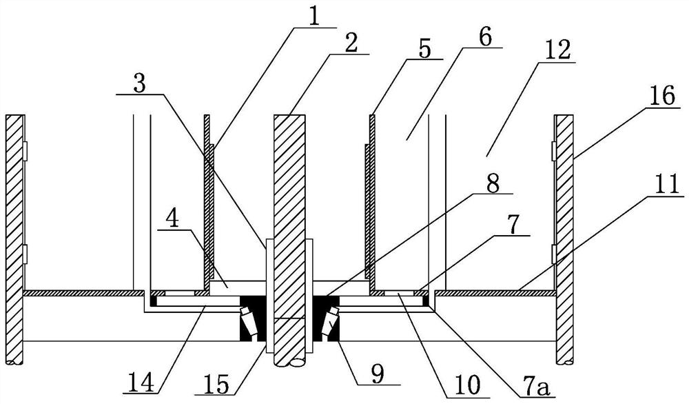
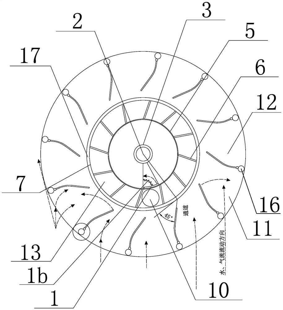
[0041] see Figure 1~3 and Figure 5 , in the embodiment of the present invention, it is suitable for the energy conversion device in the artesian hydraulic and wind power field, respectively forming the artesian hydraulic machine, the wind machine and the vortex hydraulic machine; The output end of the main shaft 2 is located at its lower end, and the output end of the main shaft 2 of the artesian hydraulic machine and the eddy current hydraulic machine is l...


PUM


Abstract

The invention relates to a device for converting water energy, water flow including non-dammed rivers, lakes, seas, oceans and artificial canal weirs, surges, wave energy and wind energy into mechanical energy, in particular to a universal multi-stage vertical shaft hydraulic and wind power conversion machine for driving a power generation device. The universal multi-stage vertical shaft hydraulic and wind power conversion machine comprises flow guide plates, a rotor disc, a stator disc and a main shaft, wherein the included angle between each flow guide plate and the tangent line of the inner circle of the stator disc is 45 degrees, so that water energy and wind energy are guided to turbine blades to generate torque, wind and water can enter from a channel between every two adjacent flow guide plates in any direction of the device, and the upstream area and the windward area of the device account for 90% or above of the total area; and meanwhile, due to the angle of the turbine blades, the wind and the water with large thrust still push the rotor disc to rotate until the flow guide plates deflect to the downstream position and the downwind position under the continuously increased thrust, and the water and the wind become flowing water and wind, so that the device is prevented from being excessively stressed.

Description

technical field [0001] The invention relates to a device for converting water energy, including non-dammed rivers, rivers, lakes, seas, oceans, artificial canals and weirs, surge, wave energy and wind energy into mechanical energy. Converting machinery to multi-stage vertical axis hydraulic wind power. Background technique [0002] Among the wind turbines, small wind turbines use wind speeds of 4-8m / s at wind speeds of 3-5 levels, and the wind collection efficiency is 0.15-0.35. s, the most commonly used is 13m / s. From the energy publicity E= ρV³ shows that the wind speed ranges from 0-60m / s from 0-17. The larger the wind level, the higher the wind speed and the greater the energy. The wind force used by the entire wind generator is basically below level 9, and the wind speed is below 25m / s. When the wind speed is 10m / s, the wind energy per square meter is 0.6kw, and when the wind speed is 15m / s, the energy is 2.025kw per square meter. When the wind is at level 9, the ...

Claims


Application Information

Patent Timeline
IPC IPC(8): F03D9/25F03D3/04F03D3/06F03B13/00F03B3/12F03B3/18F03B11/06
CPCF03D9/25F03D3/005F03D3/0418F03B13/00F03B3/121F03B3/183F03B11/06F05B2220/706F03D3/062Y02E10/20Y02E10/74
Inventor 黄始征黄渭吴辛辰黄祺瑞
Owner 黄始征
Why Eureka
Try Eureka