Mounting and fixing device for classroom roller shutter
A technology of fixing device and rolling shutter, applied in the direction of shading screen, etc., can solve the problem of indoor personnel injury and other problems
- Summary
- Abstract
- Description
- Claims
- Application Information
AI Technical Summary
Problems solved by technology
Method used
Image
Examples
Embodiment 1
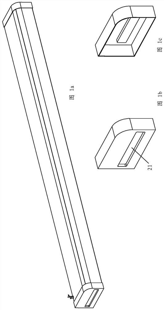
[0025] Example 1. The electric roller blind powered by a micro motor has an outer casing, and its left and right ends have end covers. Figure 1a The one shown is already a roller blind product. Since the roller blind needs to be placed on the upper edge of the window at a higher place, how to fix it and ensure the safety of the product and the safety of the ground personnel is a problem that must be carefully faced in the installation process of the roller blind product.
[0026] according to Figure 3a The left and right L brackets are constructed as shown in -b, which are suitable for carbon steel stamping parts with good rigidity and load-bearing capacity. The main board (11) of the L holder is equipped with a middle hole (111) and the horizontal hole (112) below which plays a secondary guarantee effect, and the left and right L holders can be placed on the window by means of the middle hole (111) and the horizontal hole (112). The elevation of the upper wall is fixed at...
Embodiment 2
[0032] Example 2. see Figure 8a , such as changing the structure of the above-mentioned left and right end cover concave areas (21) to an external convex dam (22) structure, the working principle of this design device that achieves the preset application purpose can be found in Figure 8b -c, where Figure 8b It shows that the nut C (5) forcibly suppresses the outer convex dam (22) of the end cover (that is, the whole roller blind product), Figure 8c Shown is the non-working unlocked state of the design device. Specifically, the nut C (5) has no obstacles at all to take out the product from the L support (or place the product downward, see the arrow in the figure).
[0033] The rest are the same as embodiment 1.
[0034] It is also worth noting that:
[0035]The cooperation between the screw hole A (141) and the nut B (4) carried on the L support end vertical plate (14) is more conducive to the stability and stability of the bolt (3). The above device can still be appli...
PUM
 Abstract
Description
Claims
Application Information
 - R&D
- Intellectual Property
- Life Sciences
- Materials
- Tech Scout
- Unparalleled Data Quality
- Higher Quality Content
- 60% Fewer Hallucinations
Browse by: Latest US Patents, China's latest patents, Technical Efficacy Thesaurus, Application Domain, Technology Topic, Popular Technical Reports.
© 2025 PatSnap. All rights reserved.Legal|Privacy policy|Modern Slavery Act Transparency Statement|Sitemap|About US| Contact US: help@patsnap.com


