Electrical equipment winding device capable of uniformly arranging electric wires
A technology of uniform arrangement of electrical equipment, applied in the direction of transportation and packaging, transportation of filamentous materials, thin material handling, etc., can solve problems such as uneven wiring, manual wire trimming, wire winding, etc.
- Summary
- Abstract
- Description
- Claims
- Application Information
AI Technical Summary
Problems solved by technology
Method used
Image
Examples
Embodiment 1
[0066] A winding device for evenly arranging wires for electrical equipment, such as figure 1 As shown, it includes a bed 1, a motor frame 2, a deceleration motor 3, a winding assembly 4 and a clamping assembly 5. A motor frame 2 is installed on the right rear of the bed 1, and a deceleration motor 3 is installed on the top of the motor frame 2. , the upper back side of the bed 1 is provided with a winding assembly 4 , the right side of the winding assembly 4 is connected with the output shaft of the deceleration motor 3 , and the winding assembly 4 is provided with a clamping assembly 5 .
[0067]When electrical workers need to wind up messy wires, they can use this winding device. First, one end of the wire is clamped by tightening the clamping assembly 5, and then the geared motor 3 is started, and the output shaft of the geared motor 3 drives the winding wire. The assembly 4 operates, so that the wire is wound on the wire winding assembly 4. After all the wires are wound, ...
Embodiment 2
[0069] On the basis of Example 1, as figure 2 and image 3 As shown, the winding assembly 4 includes a first rotating shaft 41, a coupling 42, a second rotating shaft 43, a first roller 44 and a first baffle 45, the output shaft of the gear motor 3 is connected with a first rotating shaft 41, and the bed 1. A second rotating shaft 43 is rotatably provided on the upper and rear sides. The second rotating shaft 43 slides on the bed 1. A coupling 42 is connected between the right end of the second rotating shaft 43 and the left end of the first rotating shaft 41. There is a first drum 44 , and first baffles 45 are provided on the left and right sides of the first drum 44 .
[0070] The rotation of the output shaft of the reduction motor 3 drives the rotation of the first shaft 41, thereby driving the coupling 42 to rotate, thereby driving the second shaft 43 to rotate, and then driving the first roller 44 to rotate, so as to realize the effect of wire winding. Avoid loosening ...
Embodiment 3
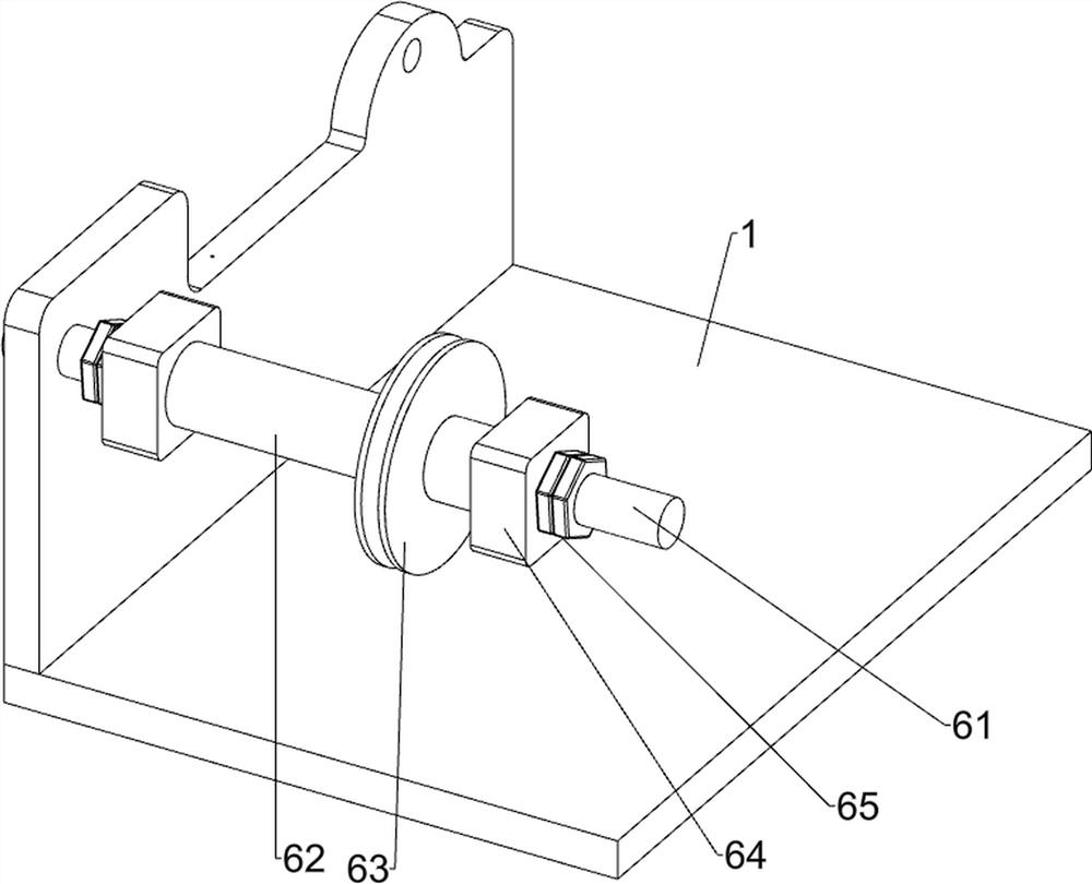
[0074] On the basis of Example 2, as Figure 4 , Figure 5 , Image 6 and Figure 7 As shown in the figure, it also includes a manual uniform wiring assembly 6. The upper left part of the upper front side of the bed 1 is provided with a manual uniform wiring component 6. The manual uniform wiring component 6 includes a double-ended screw 61, a sliding sleeve 62, and a wire wheel 63. , the first limit block 64 and the second nut 65, a double-ended screw 61 is connected to the left part of the upper front side of the bed 1, the middle of the double-ended screw 61 is provided with a sliding sleeve 62, and the sliding sleeve 62 is slidably provided with a wire wheel 63, The left and right sides of the double-ended screw 61 are provided with first limiting blocks 64 , and the left and right sides of the double-ended screw 61 are provided with second nuts 65 .
[0075] Lay the wire on the spool 63 to prevent the wire from winding during the winding process, and then adaptively dr...
PUM
 Abstract
Description
Claims
Application Information
 - Generate Ideas
- Intellectual Property
- Life Sciences
- Materials
- Tech Scout
- Unparalleled Data Quality
- Higher Quality Content
- 60% Fewer Hallucinations
Browse by: Latest US Patents, China's latest patents, Technical Efficacy Thesaurus, Application Domain, Technology Topic, Popular Technical Reports.
© 2025 PatSnap. All rights reserved.Legal|Privacy policy|Modern Slavery Act Transparency Statement|Sitemap|About US| Contact US: help@patsnap.com


