In-situ fenestration device
A window-opening and in-situ technology, which can be used in the fields of human tubular structure devices, medical science, blood vessels, etc., and can solve problems such as easy deviation of the puncture position
- Summary
- Abstract
- Description
- Claims
- Application Information
AI Technical Summary
Problems solved by technology
Method used
Image

Examples
Embodiment approach 1
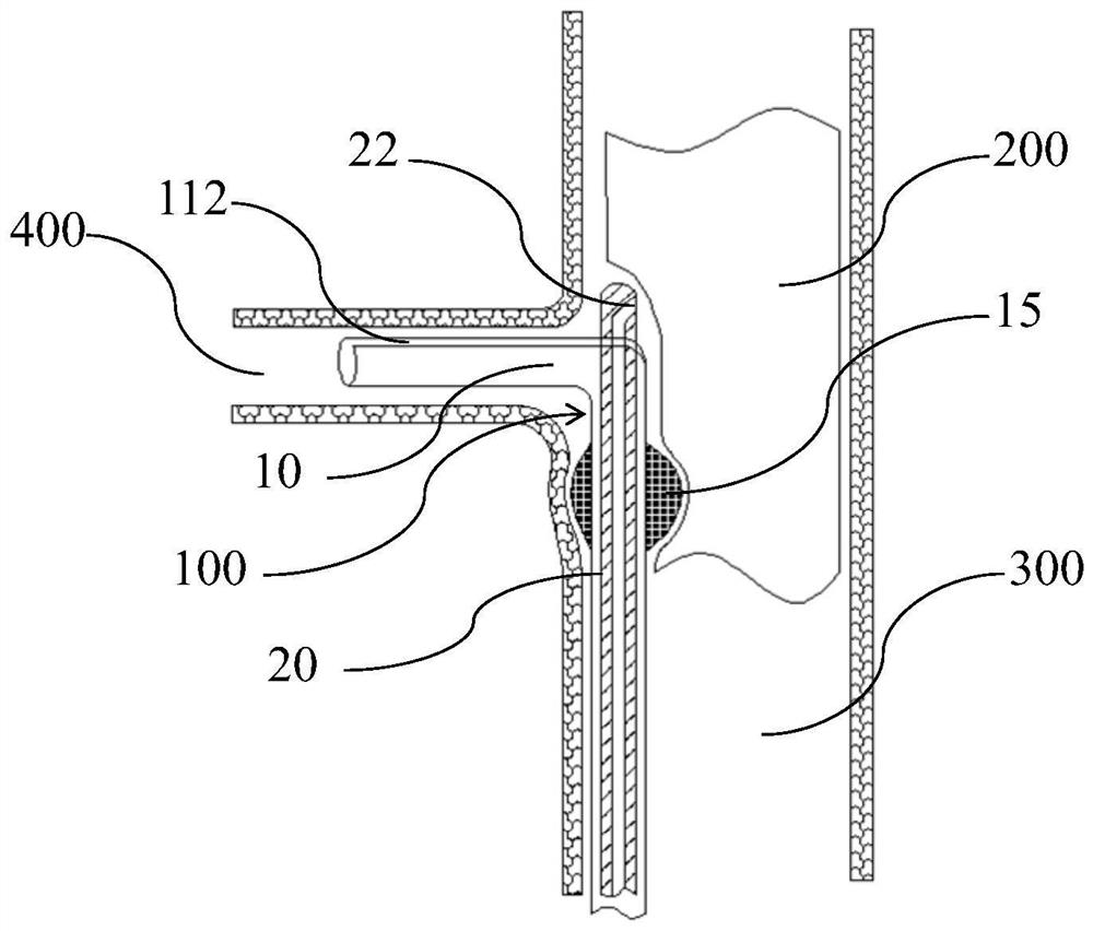
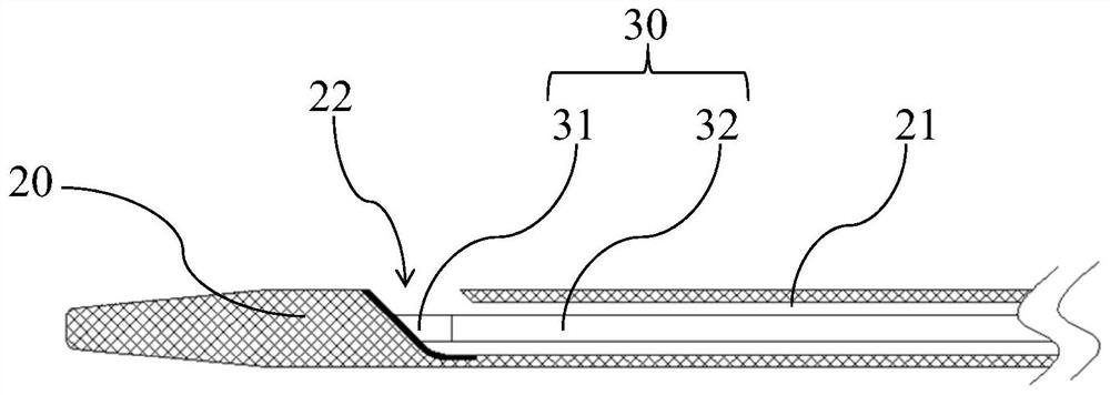
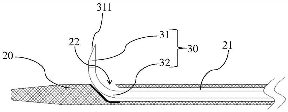
[0061] to combine Figure 1 to Figure 3 As shown, the present invention proposes an in-situ fenestration device 100 , and the in-situ fenestration device 100 includes a sheath tube 10 , a catheter 20 and a puncture member 30 . The interior of the sheath tube 10 is hollow and the side wall of the distal end is provided with a first opening 112. The catheter 20 is penetrated inside the sheath tube 10 and can move along the axial direction of the sheath tube 10. The distal end of the catheter tube 20 can pass through the first opening 112. An opening 112 protrudes to the outside of the sheath tube 10 , and the catheter 20 is provided with an opening 22 on the side wall of the distal end. The piercing member 30 is installed inside the catheter 20 and can move along the axial direction of the catheter 20. The distal end of the piercing member 30 is in a pre-curved shape in a natural state. When the distal end of the piercing member 30 reaches the position of the opening 22 , the d...
Embodiment approach 2
[0103] to combine figure 1 , Figure 17 and Figure 18 As shown, the in-situ fenestration device 100 of this embodiment is basically the same as that of the first embodiment, including the sheath tube 10 , the catheter 20 and the puncture member 30 . The interior of the sheath 10 is hollow and the side wall of the distal end is provided with a first opening 112. The catheter 20 is penetrated inside the sheath 10 and can move in the axial direction. The distal end of the catheter 20 can extend through the first opening 112. Out to the outside of the sheath tube 10 , a guide port 22 is provided on the side wall of the distal end of the catheter 20 . The puncture member 30 is installed inside the catheter 20 and can move in the axial direction. The distal end of the puncture member 30 is in a pre-curved shape in a natural state. The distal end of the stent-graft 200 is automatically bent through the access opening 22 and reversely punctures the stent-graft 200 . Further, the ...
Embodiment approach 3
[0108] to combine figure 1 and Figure 22 As shown, at least in the end wall of the distal end of the catheter 20, a guide wire channel 23 communicating with the outside of the catheter 20 is provided. Specifically, the proximal end opening of the guide wire channel 23 is opened on the side wall of the catheter 20, and The guide wire channel 23 is disposed near the barrier 40 along the axial direction of the catheter 20 , and the distal opening of the guide wire channel 23 is opened at the distal end of the catheter 20 . Since the catheter 20 usually needs to be pushed through the delivery channel established by the guide wire during the delivery process, and reaches the predetermined position, the opening 22 of the catheter 20 used for reverse fenestration is provided on the side of the distal end of the catheter 20 , so when the catheter 20 is transported with the help of a guide wire, the guide wire needs to pass through the opening 22 on the side of the catheter 20, and w...
PUM
 Abstract
Description
Claims
Application Information
 - R&D
- Intellectual Property
- Life Sciences
- Materials
- Tech Scout
- Unparalleled Data Quality
- Higher Quality Content
- 60% Fewer Hallucinations
Browse by: Latest US Patents, China's latest patents, Technical Efficacy Thesaurus, Application Domain, Technology Topic, Popular Technical Reports.
© 2025 PatSnap. All rights reserved.Legal|Privacy policy|Modern Slavery Act Transparency Statement|Sitemap|About US| Contact US: help@patsnap.com