
Method and device for drawing three-dimensional model on two-dimensional plane

A technology of 3D model and 2D plane, applied in the field of 3D modeling, to achieve the effect of improving efficiency and convenience, improving accuracy and reducing complexity

Pending Publication Date: 2021-04-06
武汉达梦数据技术有限公司
View PDF7 Cites 0 Cited by
  • Summary
  • Abstract
  • Description
  • Claims
  • Application Information

AI Technical Summary

Problems solved by technology

[0004] In view of this, it is necessary to provide a method and device for drawing a three-dimensional model on a two-dimensional plane, in order to solve the problem of how to propose a high-efficiency, high-precision three-dimensional model building method in the prior art

Method used


Image

  • Method and device for drawing three-dimensional model on two-dimensional plane
  • Method and device for drawing three-dimensional model on two-dimensional plane
  • Method and device for drawing three-dimensional model on two-dimensional plane

Examples


Embodiment 1

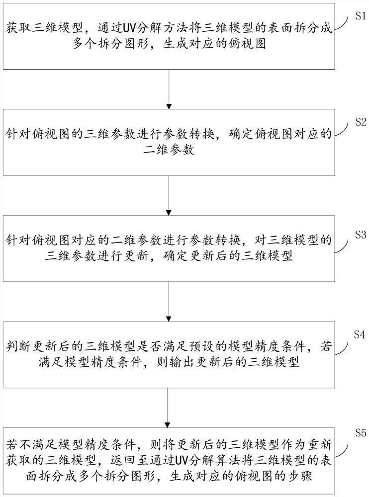
[0047] An embodiment of the present invention provides a method for drawing a three-dimensional model on a two-dimensional plane, combining figure 1 look, figure 1 It is a schematic flow chart of the method for drawing a three-dimensional model on a two-dimensional plane provided by the present invention. The above-mentioned method for drawing a three-dimensional model on a two-dimensional plane includes steps S1 to S5, wherein:

[0048] In step S1, the three-dimensional model is obtained, and the surface of the three-dimensional model of the UV decomposition method is split into multiple split graphics by the UV decomposition method to generate a corresponding top view;

[0049] In step S2, perform parameter conversion for the three-dimensional parameters of the top view of the UV decomposition method, and determine the two-dimensional parameters corresponding to the top view of the UV decomposition method;

[0050] In step S3, perform parameter conversion for the two-dimens...

Embodiment 2

[0084] An embodiment of the present invention provides a device for drawing a three-dimensional model on a two-dimensional plane, combining Figure 8 look, Figure 8 A schematic structural diagram of a device for drawing a three-dimensional model on a two-dimensional plane provided by the present invention, wherein the device 800 for drawing a three-dimensional model on a two-dimensional plane includes:

[0085] The top view generation unit 801 is used to acquire the three-dimensional model, split the surface of the three-dimensional model by the UV decomposition method into multiple split graphics by the UV decomposition method, and generate a corresponding top view;

[0086] The two-dimensional conversion unit 802 is used to perform parameter conversion for the three-dimensional parameters of the top view of the UV decomposition method, and determine the two-dimensional parameters corresponding to the top view of the UV decomposition method;

[0087] The three-dimensional u...

Embodiment 3

[0090] An embodiment of the present invention provides a device for drawing a three-dimensional model on a two-dimensional plane, including a processor and a memory, and a computer program is stored in the memory. When the computer program is executed by the processor, the above-mentioned three-dimensional drawing on the two-dimensional plane is realized. The method of the model.


PUM


Abstract

The invention relates to a method and device for drawing a three-dimensional model on a two-dimensional plane, and the method comprises the steps: obtaining the three-dimensional model, and generating a corresponding top view through a UV decomposition method; performing parameter conversion on the three-dimensional parameters of the top view, and determining two-dimensional parameters corresponding to the top view; performing parameter conversion on the two-dimensional parameters corresponding to the top view, updating the three-dimensional parameters of the three-dimensional model, and determining the updated three-dimensional model; judging whether the updated three-dimensional model meets a model precision condition or not, and outputting the updated three-dimensional model if the updated three-dimensional model meets the model precision condition; and if the model precision condition is not met, taking the updated three-dimensional model as a re-acquired three-dimensional model, and returning to the step of generating the corresponding top view through the UV decomposition method. The updated three-dimensional model is generated through UV decomposition and coordinate conversion, and UV decomposition is performed on the updated three-dimensional model again until the precision requirement is met, so that the 3D modeling efficiency and convenience are improved.

Description

technical field [0001] The invention relates to the technical field of three-dimensional modeling, in particular to a method and device for drawing a three-dimensional model on a two-dimensional plane. Background technique [0002] In the process of developing 3D model software products, it is usually necessary to combine and package the already produced models to form a 3D model product with a certain scale. In this process, coordinate transformation technologies such as model movement and rotation are often used. At present, most of the 3D software products on the market implement designers that operate in 3D space, and this modeling method has some disadvantages. On the one hand, the existing modeling methods perform multiple transformation operations in 3D space. Due to the complexity of 3D space, the accuracy of the operation is not high. It is difficult to accurately draw the model; on the other hand, the existing modeling method is complex and cumbersome in the thre...

Claims


Application Information

Patent Timeline
Patent Type & Authority Applications(China)
IPC IPC(8): G06T3/00G06T3/60G06T17/00
CPCG06T3/60G06T17/00G06T3/06
Inventor 段攀邵宗前石元春赵寅张永强李庄庄
Owner 武汉达梦数据技术有限公司
Learn More