
Knife-shaped hairpin chamfering facility with screening and feeding functions

A knife-shaped and functional technology, applied in the field of knife-shaped hairpin chamfering equipment, can solve problems such as low efficiency, endangering the safety of producers' operation, wasting labor, etc., and achieve the effect of improving production efficiency

Pending Publication Date: 2021-04-06
重庆德森诺科技有限公司
View PDF13 Cites 1 Cited by
  • Summary
  • Abstract
  • Description
  • Claims
  • Application Information

AI Technical Summary

Problems solved by technology

[0003] The existing processing equipment for hairpin accessories often has the following problems: the knife-shaped hairpins are produced in the form of wool after being pre-pressed with a plate, and then the wool needs to be chamfered to make the finished product more beautiful and comfortable to wear. The knife-shaped hairpins discharged in the form of wool are usually placed in irregular positions. In the traditional manufacturing process, it is necessary to manually sort out the placement of the wool, which is inefficient and wastes labor. At the same time, the sharp corners of the wool can easily endanger the safety of the producer. Therefore, there is an urgent need for an automatic chamfering equipment with the functions of screening directional feeding and batch chamfering, replacing manual labor with highly automated production lines, and improving production efficiency

Method used


Image

  • Knife-shaped hairpin chamfering facility with screening and feeding functions
  • Knife-shaped hairpin chamfering facility with screening and feeding functions
  • Knife-shaped hairpin chamfering facility with screening and feeding functions

Examples


Embodiment Construction

[0029]The following will clearly and completely describe the technical solutions in the embodiments of the present invention with reference to the accompanying drawings in the embodiments of the present invention. Obviously, the described embodiments are only some, not all, embodiments of the present invention.

[0030] In the description of the present invention, unless otherwise stated, the meaning of "plurality" is two or more; the terms "upper", "lower", "left", "right", "inner", "outer" , "front end", "rear end", "head", "tail", etc. indicate the orientation or positional relationship based on the orientation or positional relationship shown in the drawings, and are only for the convenience of describing the present invention and simplifying the description, rather than Indicates or implies that the device or element referred to must have a particular orientation, be constructed and operate in a particular orientation, and therefore should not be construed as limiting the ...


PUM


Abstract

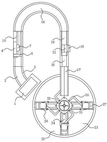
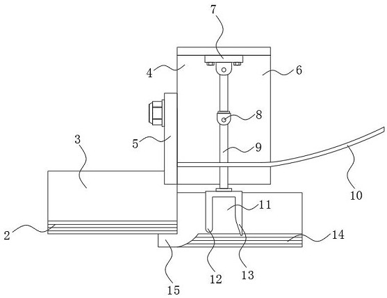
The invention discloses a knife-shaped hairpin chamfering facility with screening and feeding functions, and relates to the technical field of ornament processing. The facility specifically comprises a feeding end, a reverse material screening mechanism, a directional feeding mechanism, a synchronous chamfering mechanism and a cam divider, wherein a lifting rail is arranged on one side of the feeding end. According to the knife-shaped hairpin chamfering facility with the screening and feeding functions, due to the fact that the reverse material screening mechanism is arranged, the known track distance of the lifting track only allows blanks in the vertical direction to pass through, and the reverse material screening mechanism only needs to identify and screen the direction of the large diameter or the small diameter when the blanks pass through the mechanism. In a traditional manufacturing technology, when visual inspection equipment and other equipment or the manual screening mode is used, the production cost of an enterprise can be undoubtedly and greatly increased, and the traditional manufacturing technology is not suitable for large-batch low-cost workpiece production, and therefore the knife-shaped hairpin reverse material recognition screening which is achieved through a simple mechanical structure and a simple physical principle has the irreplaceable advantages of low cost, accuracy, efficiency, easy and convenient maintenance and the like.

Description

technical field [0001] The invention relates to the technical field of jewelry processing, in particular to a knife-shaped hairpin chamfering device with the function of screening and feeding materials. Background technique [0002] Ornaments are items used for decoration. The general purpose is to beautify the personal appearance, decorate the living room, beautify the public environment, and decorate the car; the ornaments can be divided into the following categories according to the purpose: home accessories, clothing accessories, car accessories, etc.; hairpins are used as beautification Personal appearance jewelry is a kind of jewelry used to fix and decorate the hair. People are always impressed by the exquisite effect they embellish, and the knife-shaped hairpin is one of the huge types of hairpins with a simple shape. But it is exquisite, and it is more and more sought after by the young people because of its easy matching with different kinds of clothing. [0003] ...

Claims


Application Information

Patent Timeline
IPC IPC(8): B65G47/256B65G47/248
CPCB65G47/256B65G47/248
Inventor 王燕张创振
Owner 重庆德森诺科技有限公司
Learn More