
Patsnap Eureka
For R&D, Patsnap Eureka makes reading and utilizing patents & technical documents easy.
Patsnap Eureka AIR
Designed for self-driven R&D workflows. Generate viable solutions, solve complex R&D challenges, empower your innovation with AI.

Patsnap Eureka Materials
Designed for material experts only. Revolutionize your material R&D, from search, analyze, to developing new materials.

TechResearch
Generate reliable direction feasibility study reports for your R&D in just a few steps.

TechSeek
Discover and master advanced knowledge NOW. Basics, ideas, possibilities, all at once.

TechMind
As an expert in R&D Theories, TechMind can generates customized viable solutions instantly.

TechRisk
Analyze your overall solution with one click, know your potential R&D risks in advance.

TechMonitor
Get weekly tech updates, stay abreast of the latest tech innovations and key insights.
A conveying device, production line and method capable of automatic decoupling and reset
A conveying device, the technology of automatic decoupling, applied in the direction of conveyor, transportation and packaging, can solve the problems of difficult continuous work and complex structure, and achieve the effect of preventing accidental decoupling, high economic efficiency and strong flexibility
- Summary
- Abstract
- Description
- Claims
- Application Information
AI Technical Summary
Problems solved by technology
Method used
Image

Examples
Embodiment 2
[0051] This embodiment discloses a production line, which is equipped with the conveying mechanism described in Embodiment 1 that can be automatically unhooked and reset. The production line can use the existing production line that needs pendant conveying, and its specific structure will not be described in detail here. .
Embodiment 3
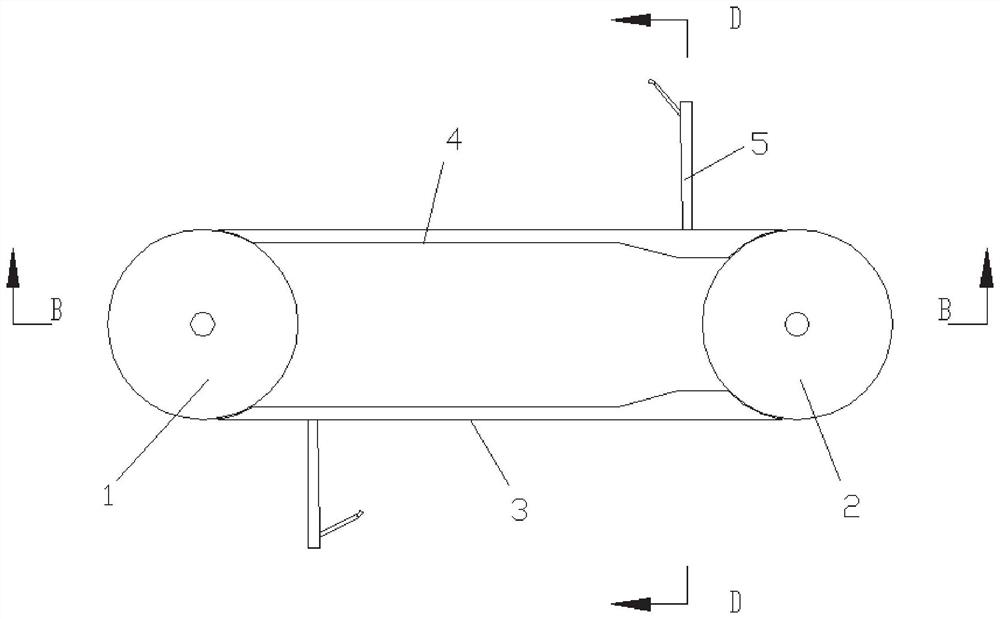
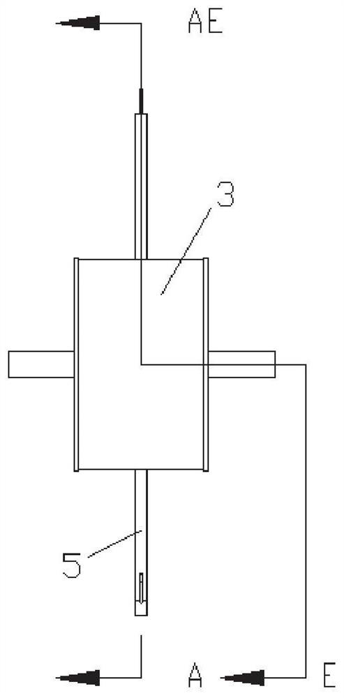
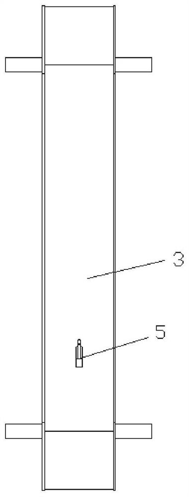
[0053] This embodiment discloses the working method of the conveying mechanism described in Embodiment 1, as Figure 9 As shown, the material is hung on the hook in the hook mechanism where the guide rod is in contact with the non-groove position of the guide plate. At this time, the guide rod is in contact with the E section of the guide plate. When it is transported to the position where it needs to be unhooked and dropped, the end of the guide rod moves from section D to section C and contacts the bottom groove surface of the groove. At this time, the guide rod moves along the axis of the housing under the action of the spring, and the hook rotates. The angle between the guide rod and the guide rod gradually increases, the material slides from the hook under the action of gravity, and the decoupling is completed, the hook mechanism continues to move with the conveyor belt, the end of the guide rod moves from section B to section A, and moves out of the groove, the guide rod ...
PUM
 Abstract
Description
Claims
Application Information
 - R&D Engineer
- R&D Manager
- IP Professional
- Industry Leading Data Capabilities
- Powerful AI technology
- Patent DNA Extraction
Browse by: Latest US Patents, China's latest patents, Technical Efficacy Thesaurus, Application Domain, Technology Topic, Popular Technical Reports.
© 2024 PatSnap. All rights reserved.Legal|Privacy policy|Modern Slavery Act Transparency Statement|Sitemap|About US| Contact US: help@patsnap.com